Electronic vent valve

a technology of electronic vent valve and valve body, which is applied in the direction of brake system, brake components, transportation and packaging, etc., can solve the problems of affecting the operation of the brake valve, so as to achieve reliable operation and efficient manufacturing

Inactive Publication Date: 2002-11-14
WESTINGHOUSE AIR BRAKE CO
View PDF0 Cites 24 Cited by
  • Summary
  • Abstract
  • Description
  • Claims
  • Application Information

AI Technical Summary

Benefits of technology

[0016] One object of the present invention is the provision of an electronic vent valve for attachment to the brake pipe of an electronically controlled pneumatic braking system for quickly and precipitously lowering the brake pipe pressure in response to a received electrical signal indicating the initiation of an emergency braking condition, thereby ensuring that the control valve of the pneumatic braking system will respond to the rapidly lowered brake pipe pressure by supplying an appropriate compressed air charge from the onboard auxiliary / emergency reservoirs to the brake cylinders so as to initiate the desired emergency braking action.
[0020] A yet further object of the present invention is the provision of such an electronic vent valve that is reliable in operation and efficient in manufacture.

Problems solved by technology

However, a limitation of such a conventional pneumatic braking system described above that has been long appreciated is the delay in braking that occurs as the change in brake pipe pressure propagates along the length of a train.
However, on long trains, particularly long freight trains, brake pipe pressure changes, even an emergency brake pipe pressure reduction, can take up to one-half minute to propagate the length of the train.

Method used


Image

  • Electronic vent valve
  • Electronic vent valve
  • Electronic vent valve

Examples


first embodiment

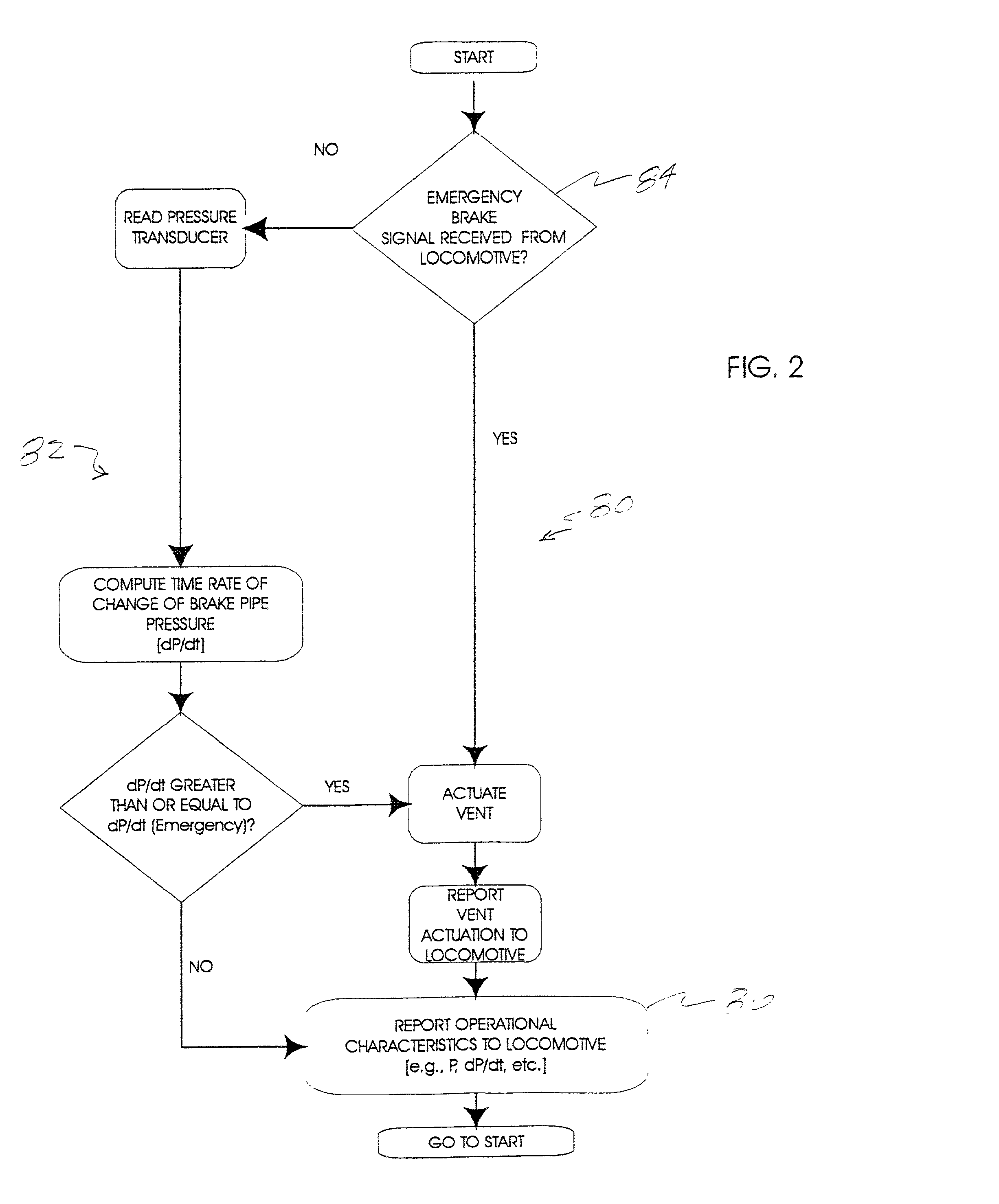
[0026] FIG. 2 is a flow chart showing an algorithmic procedure implemented by a microprocessor component of the electronic vent valve of FIG. 1.

second embodiment

[0027] FIG. 3 is a flow chart showing an algorithmic procedure implemented by a microprocessor component of the electronic vent valve of FIG. 1.

third embodiment

[0028] FIG. 4 is a flow chart showing an algorithmic procedure implemented by a microprocessor component of the electronic vent valve of FIG. 1.

[0029] Prior to proceeding to a much more detailed description of the present invention, it should be noted that identical components which have identical functions have been identified with identical reference numerals throughout the several views illustrated in the drawing Figures for the sake of clarity and understanding of the invention.

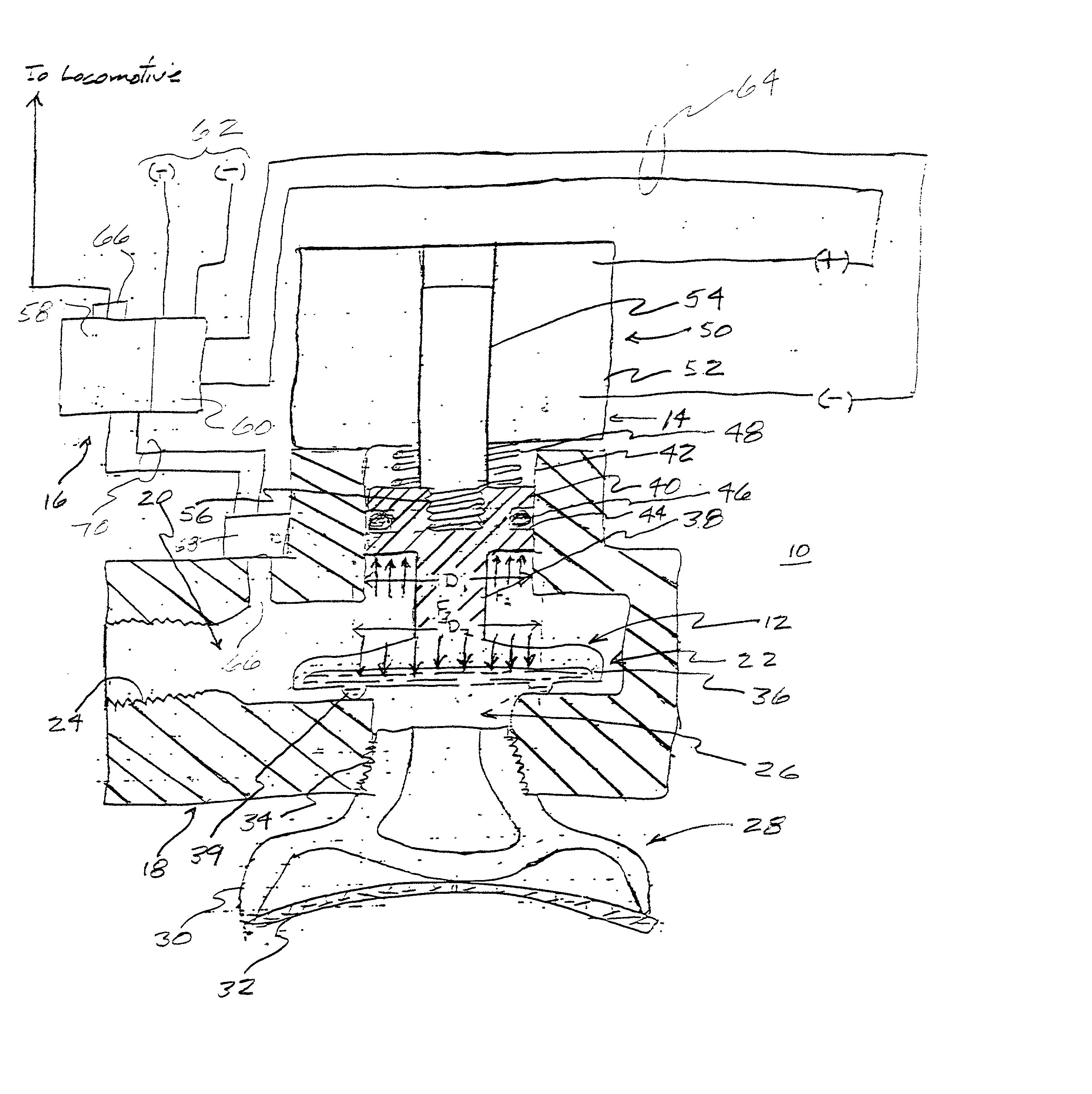
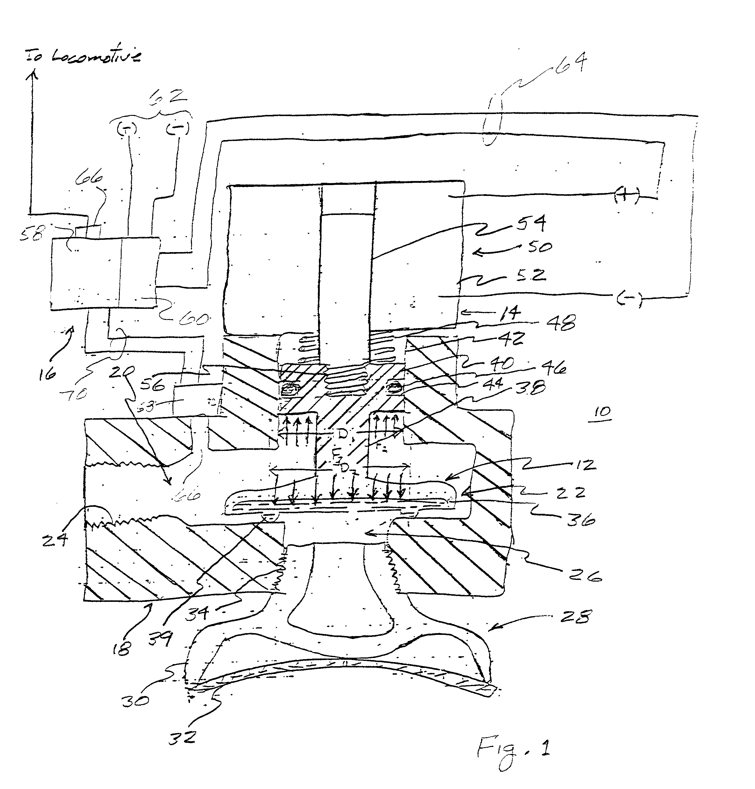
[0030] Referring now to FIG. 1, an electronic vent valve constructed according to the present invention and designated by reference numeral 10 generally includes a valve 12, an electrically operated actuator 14 for moving the valve 12 between an open position and a closed position and a control circuit 16 for controlling the electrically operated actuator 14 so as to cause the electrically operated actuator 14 to move the valve 12 between the open and closed position in accordance with algorithmic procedu...


PUM


Abstract

An electronic vent valve for an electronically controlled pneumatic (ECP") braking system having a plurality of braking sites at which a braking force can be applied. The ECP braking system includes a master controller processing circuit, individual braking control units located proximate each of the braking sites and a brake pipe supplying compressed air to the braking sites. The electronic vent valve is in fluid communication with the compressed air carried by the brake pipe and has an open position for substantially venting the compressed air from the brake pipe and a closed position for substantially retaining the compressed air within the brake pipe. The electronic vent valve includes a control circuit for causing the valve to open during emergency braking operations, thereby assuring a rapid decrease in the brake pipe pressure. The control circuit preferably includes a brake pipe pressure sensor and a microprocessor for calculating a rate of change of the brake pipe pressure (dP / dt) and for causing the valve to open whenever the calculated rate of change of brake pipe pressure exceeds a threshold value. The control circuit can additionally cause the valve to open in response to a direct command from the master controller and can transmit to the master controller various operational characteristics of the braking system and the microprocessor itself.

Description

CROSS-REFERENCES TO RELATED APPLICATIONS[0001] The present application is directed to similar subject matter as is disclosed in U.S. patent application Ser. No. 09 / 044,352 filed on Mar. 19, 1998 by Angel P. Bezos and entitled "Improved AAR Compliant Electronic Braking System" and in U.S. patent application No. ______ filed on ______ by Robert C. Kull and entitled "Locomotive to ECP Brake Conversion System". The subject matter disclosed in the above cross-referenced copending U.S. patent applications is hereby expressly incorporated by reference with the same effect as if fully set forth herein.[0002] The present invention relates, in general, to pneumatic braking systems such as are typically employed on rail transport vehicles (e.g., trains) and other relatively large wheeled transport vehicles (e.g., heavy trucks). More particularly, the present invention relates to a so-called "electronically controlled pneumatic" (hereinafter "ECP") type of braking system for such vehicles, most...

Claims


Application Information

Patent Timeline
Patent Type & Authority Applications(United States)
IPC IPC(8): B60T11/32B60T13/66
CPCB60T13/665B60T11/326
Inventor CUNKELMAN, BRIAN L.
Owner WESTINGHOUSE AIR BRAKE CO
Why Eureka
Try Eureka