Electric toothbrush structure

a toothbrush and structure technology, applied in the direction of brushes, carpet cleaners, cleaning equipment, etc., can solve the problems of easy transmission malfunction and not only looks complex

Inactive Publication Date: 2002-11-28
SHUMMI ENTERPRISE
View PDF0 Cites 75 Cited by
  • Summary
  • Abstract
  • Description
  • Claims
  • Application Information

AI Technical Summary

Problems solved by technology

For an example, the U.S. Pat. No. 6,000,083, the patent depends the connection of a plurality of outer gears to do the power transmission, but such kind of transmiss...

Method used


Image

  • Electric toothbrush structure
  • Electric toothbrush structure
  • Electric toothbrush structure

Examples


Embodiment Construction

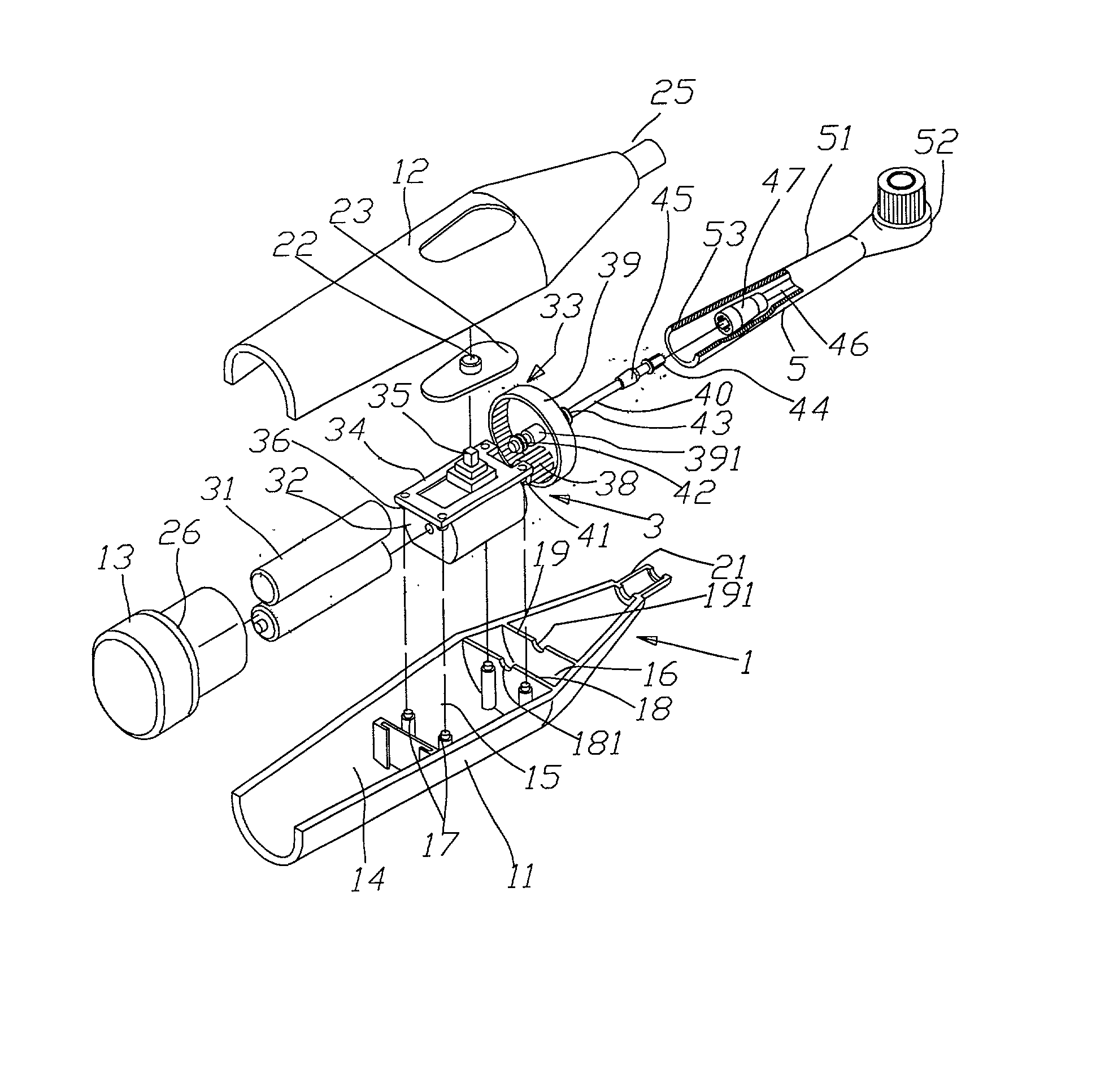
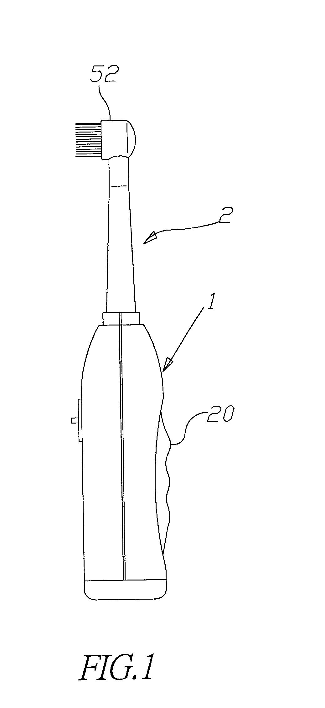
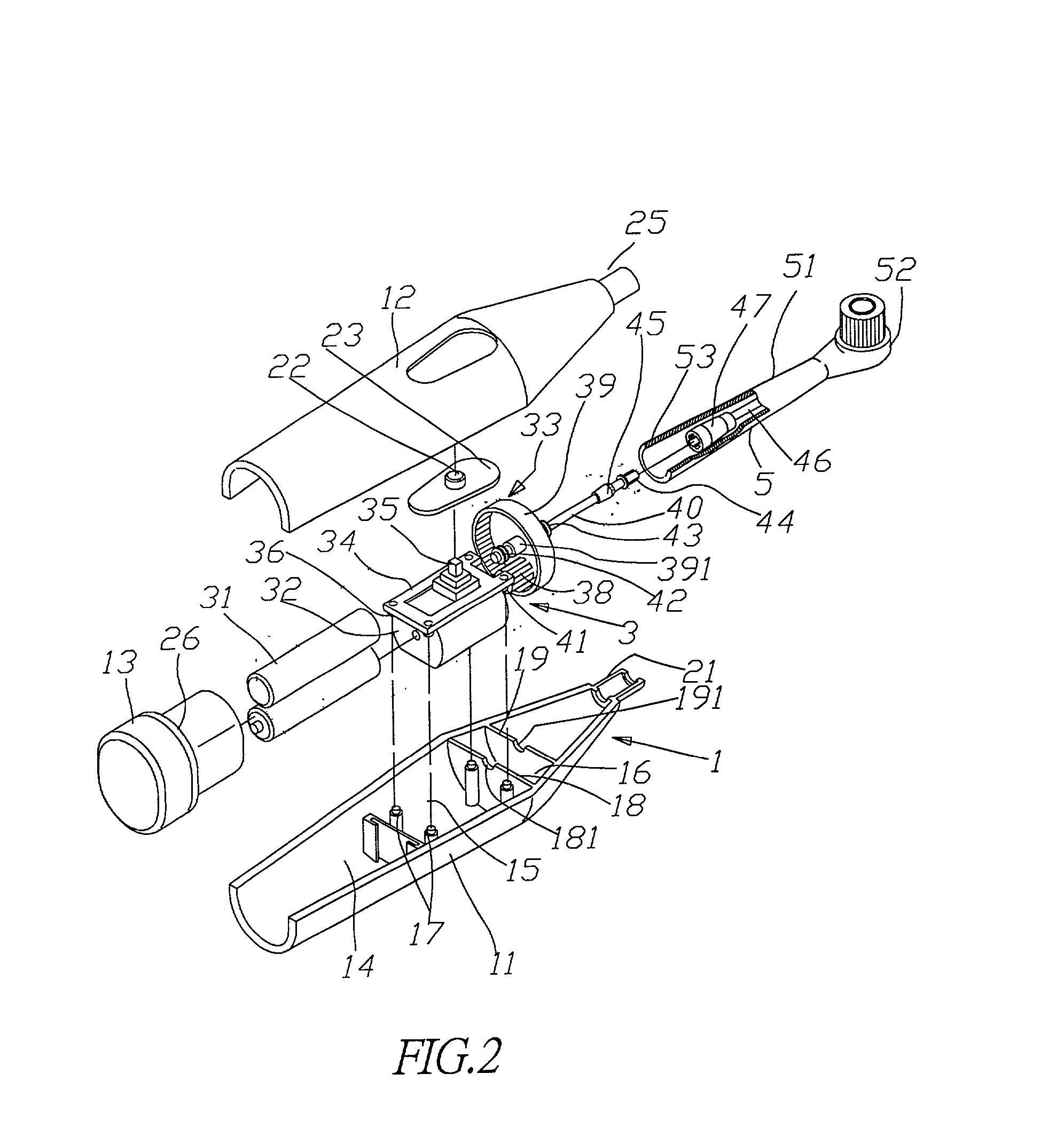
[0011] Please refer to FIG. 1 and 2, an electric toothbrush structure of the present invention comprises a block handle 1, power transmission device 3 and blockhead 5, the block handle 1 comprises a rear housing 11, front housing 12 and rear cover 13. A battery room 14, electric motor room 15 and transmission room 16 are disposed in the rear housing 11. Hollow pillars 17 are disposed at the four corners of the electric motor room 15, and a first supporting plate 18 and second supporting plate 19 are disposed at two sides of the transmission room 16, A first groove 181 and second groove 191 are disposed at the first supporting plate 18 and second supporting plate 19 respectively. Furthermore, a soft rubber and wave type grasp is disposed at the backside surface of the rear housing 11 (as shown in FIG. 1); a noose 21 is disposed at the front end of the rear housing 11. A button 22 and button cover 23 are installed on the front housing 12, that is buckled up with the rear housing 11, p...


PUM


Abstract

A electric toothbrush structure comprises a block handle, power transmission device and blockhead; the power transmission device at least comprises a electric motor and transmission device, and the transmission consists of a outer gear, inner gear and connecting rod, the outer gear is connected to the shaft of the electric motor, and meshes with it inside the inner gear, the connecting rod is connected to the shaft of the inner gear, and a crooked shaft is disposed at the position of the connecting rod corresponding to the blockhead. The blockhead is connected to the block handle, it comprises a blockhead tube and circular head, the blockhead is used to accept the connecting rod, and circular head is pivoted to the front end of the blockhead, a groove, which is disposed at the bottom end of the circular head, is used to accept and connect with the crooked shaft of the connecting rod and driven by it to rotate left and right.

Description

[0001] The present invention relates to an electric toothbrush, and more particularly to an electric toothbrush structure, which can do deceleration and enforcement transmission, easy assembly and less malfunction.TECHNICAL BACKGROUND[0002] Generally, the rotation of the blockhead of the conventional electric toothbrush is mainly driven by the power transmission mechanics inside the toothbrush to clean teeth; the power transmission mechanics of the toothbrush is a main structure design part of it. For an example, the U.S. Pat. No. 6,000,083, the patent depends the connection of a plurality of outer gears to do the power transmission, but such kind of transmission mechanics is connected simply through those gears, so, its structure not only looks complex and uneasy to be assembled, but also cause transmission malfunction easily. Therefore, how to develop a transmission mechanics of an electric toothbrush that can attains deceleration, force augmentation and compactness in structure i...

Claims


Application Information

Patent Timeline
IPC IPC(8): A61C17/34
CPCA61C17/3436
Inventor LI, MING-KUEI
Owner SHUMMI ENTERPRISE
Why Eureka
Try Eureka