Electromagnetically actuated valve, especially for hydraulic braking systems in motor vehicles

a technology of electric motor and valve body, which is applied in the direction of braking system, process and machine control, instruments, etc., can solve the problems of increased expenditure of structural design of pole body and solenoid armature, inconvenient operation, and inability to meet the requirements of the principle of solenoid plunger, etc., to achieve stable control behavior of the valve, reduce the force effect, and simple design

Inactive Publication Date: 2002-12-05
TECHLAND RES +1
View PDF12 Cites 23 Cited by
  • Summary
  • Abstract
  • Description
  • Claims
  • Application Information

AI Technical Summary

Benefits of technology

0005] In contrast to the proportioning valve mentioned initially, the electromagnetically actuated valve according to the invention having the features in claim 1 has the advantage that it has the simple design of a two-position valve with a flat-type armature but behaves like a proportioning valve. Since, with the flat-type armature, the lines of flux of the magnetic circuit in the working air gap basically extend between the facing-each-other, flat front sides of pole body and solenoid armature, radial tolerances have little effect in this design. Moreover, the design of the seat valve and push-rod region contributes to a stable control behavior of the valve according to the invention working as pressure-control valve: the pressure prevailing on the side of the pressure-medium inlet supports the magnetic force to open the seat valve. Pressure medium emerging from the valve seat is directed without turbulence along the shutoff member and the push rod against the solenoid armature and exerts an opening effect. As the pressure differential between pressure-medium inlet and pressure-medium outlet decreases, this force effect diminishes, and the valve reaches a stable final position of the seat valve when the pressure at the outlet adjusted as a function of flow is reached. This control procedure takes place with dynamics and control quality that suffices for many applications.
0006] An advantageous design of the valve according to the invention is described in claim 2.

Problems solved by technology

The known valve has the disadvantage, however, that the solenoid plunger principle requires increased expenditures in the structural design of the pole body and solenoid armature.
This, in turn, requires a costly guidance of the solenoid armature with low guidance play, because transversal forces on the solenoid armature can lead to functional failings.
The known valve is therefore costly to manufacture.

Method used


Image

  • Electromagnetically actuated valve, especially for hydraulic braking systems in motor vehicles
  • Electromagnetically actuated valve, especially for hydraulic braking systems in motor vehicles
  • Electromagnetically actuated valve, especially for hydraulic braking systems in motor vehicles

Examples


Embodiment Construction

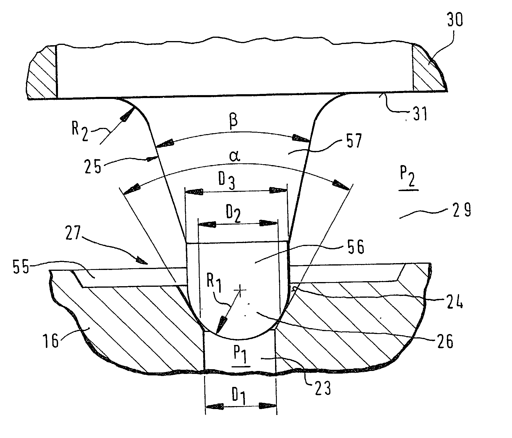
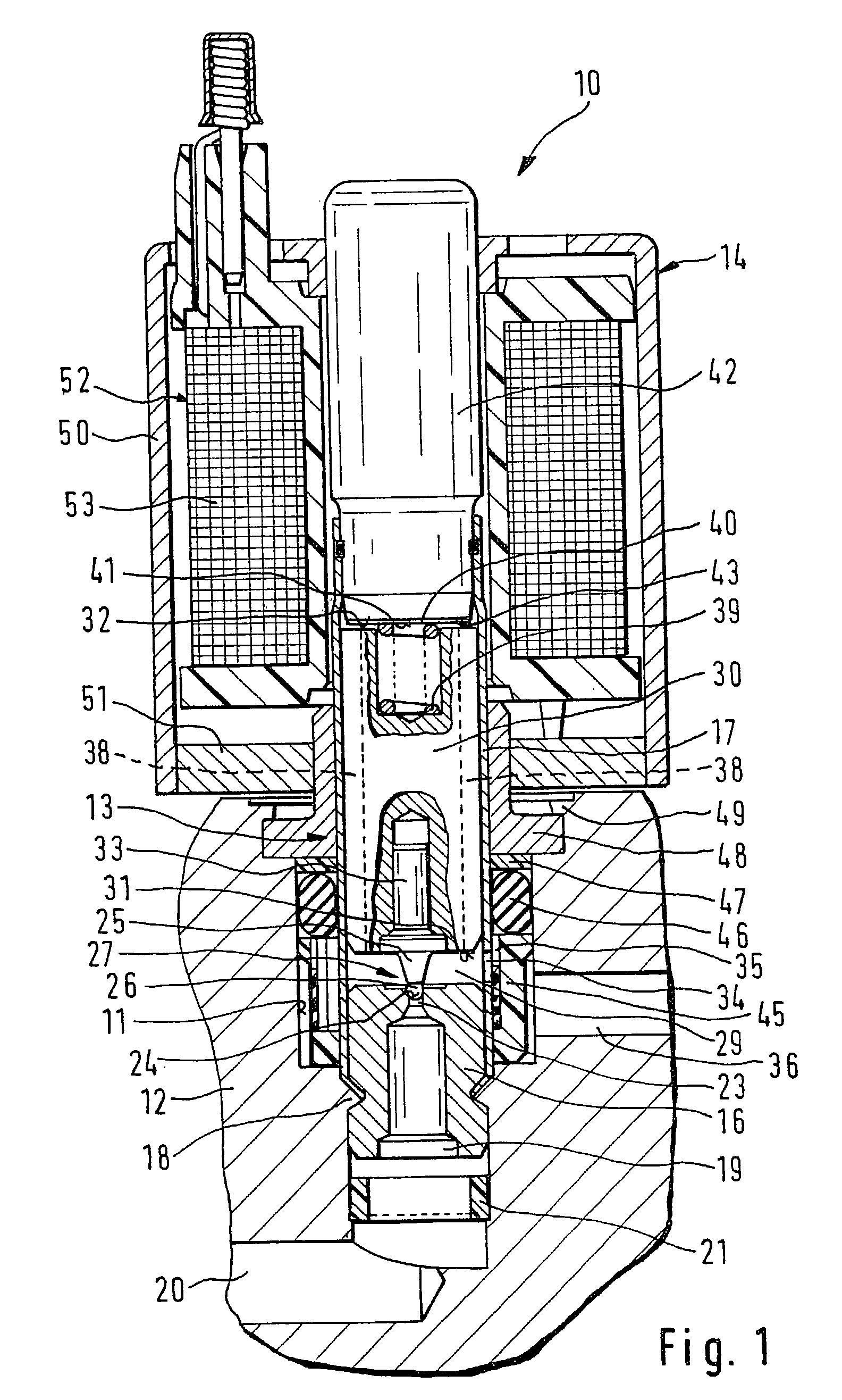
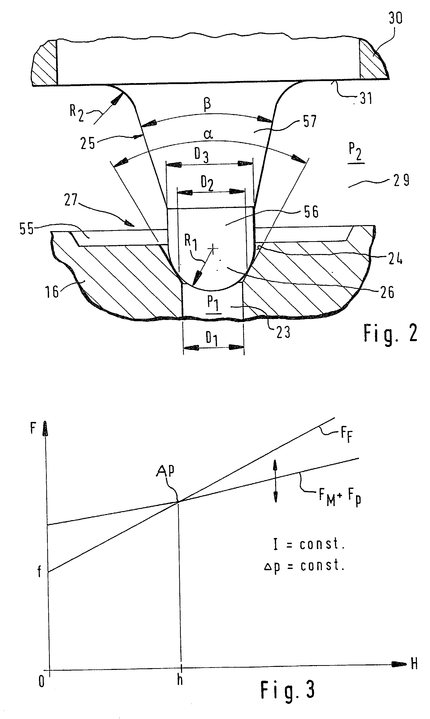
[0011] An electromagnetically actuated valve 10 shown in the drawing in FIG. 1 for hydraulic brake systems in motor vehicles, e.g., power-brake systems according to DE 195 46 647 A1, basically comprises two assemblies: a hydraulic portion 13 secured in a stepped bore 11 of a valve block 12, and an electrical portion 14 fitted onto the hydraulic portion.

[0012] The hydraulic portion 13 of the valve 10 has a longitudinally penetrating valve body 16 that is connected to an armature guide sleeve 17. The valve body 16 and the armature guide sleeve 17 are secured in the stepped bore 11 of the valve block 12 by means of a first caulked joint 18. The valve body 16 comprises a pressure-medium inlet 19 of the valve 10 that is connected to an afflux passage 20 for discharging pressure medium at the base of the stepped bore 11. A filter disc 21 is situated in the stepped bore 11 between the pressure-medium inlet 19 and the afflux passage 20.

[0013] The valve body 16 is provided with an afflux bor...


PUM


Abstract

The valve (10) has a seat valve (27) comprising a hollow cone-shaped valve seat (24) and an hemispherical shutoff element (26). An afflux bore (23) having contact with a pressure-medium inlet (19) discharges centrically into the valve seat (24). A solenoid armature (30) acting upon the seat valve (27) in opening fashion grips a push rod (25) comprising the shutoff element (26), which said solenoid armature cooperates with a pole body (42) according to the flat-type armature principle. A preloaded return spring (39) acting on the seat valve (27) in closing fashion is arranged between the pole body (42) and the solenoid armature (30). The valve (10) works as a proportioning valve, because, in addition to a suitable design of the seat valve (27) and push rod (25), the magnetic force is infinitely variable and, together with a hydraulic force, has a monotonously increasing course as the valve opening stroke increases, while the spring force-which also has a monotonously increasing course as the valve opening stroke increases-has a positive slope that is greater than that of the course of the magnetic and hydraulic force.

Description

RELATED ART[0001] The invention is based on an electromagnetically actuated valve according to the general class in claim 1.[0002] A valve is already known (DE 41 34 490 A1) that is designed as a proportioning pressure-control valve. To obtain good control behavior, the known pressure-control valve equipped with a seat valve closed without current is designed according to the solenoid plunger principle, that is, the pole body has a recess on the front side into which the basically cylindrical solenoid armature plunges more or less deeply as a function of an electric current supplied to an electrical winding enclosing the pole body. The magnetic force acting upon the solenoid armature is thereby supported by a hydraulic force in the sense of opening the seat valve, while the force of the return spring counteracts these forces.[0003] The known valve has the disadvantage, however, that the solenoid plunger principle requires increased expenditures in the structural design of the pole b...

Claims


Application Information

Patent Timeline
Patent Type & Authority Applications(United States)
IPC IPC(8): B60K31/06B60T15/36B60T8/36B60T13/68B60T15/02F16K31/06
CPCB60T15/028B60T8/367B60T8/36
Inventor HOFMANN, DIRKSCHWARZ, HANS-FRIEDRICHHAHL, GERHARDSCHUBITSCHEW, VALENTIN
Owner TECHLAND RES
Why Eureka
Try Eureka