Apparatus and method for in-process high power variable power division

a high-power variable and power division technology, applied in the field of microwave and rf processing, can solve the problem that the power division ratio cannot be easily altered, and achieve the effects of preventing interference, high electrical conductivity, and preventing damage to the mechanism

Inactive Publication Date: 2002-12-05
RF TECH A FERRITE +1
View PDF0 Cites 20 Cited by
  • Summary
  • Abstract
  • Description
  • Claims
  • Application Information

AI Technical Summary

Benefits of technology

0048] The actual changing of the power division ratio is accomplished by the combination of capacitive probes 25, 26 and inductive tuner posts 40, 41 and 42, 43. In the particular embodiment disclosed, the inductive posts 40, 41 & 42, 43 are all round aluminum bars some 1+1/2" in diameter and 4.870" long. The posts are each 1" from the adjoining wall of the waveguide 15, separated from each other by 7.75". The edge contact surface of the posts are each about 0.075" with a relief having a depth of about 0.030" comprising the rest of the surface. This is to ensure secure electrical contact to transform the high surface currents that pass along the outer surface of the inductive posts (skin effect). These inductive posts 40, 41 & 42, 43 are located in pairs 40, 41 & 42, 43 separated

Problems solved by technology

This design has the disadvantage that, once it is set (typically in the me

Method used


Image

  • Apparatus and method for in-process high power variable power division
  • Apparatus and method for in-process high power variable power division
  • Apparatus and method for in-process high power variable power division

Examples


Embodiment Construction

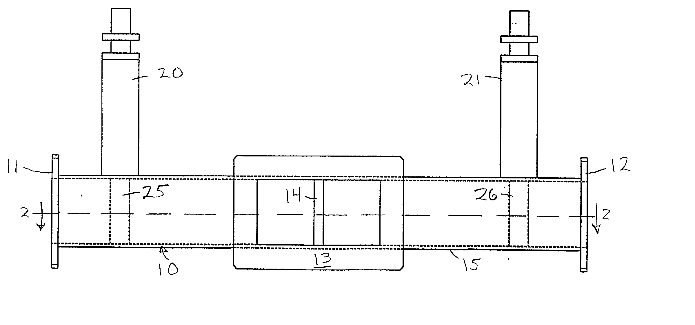
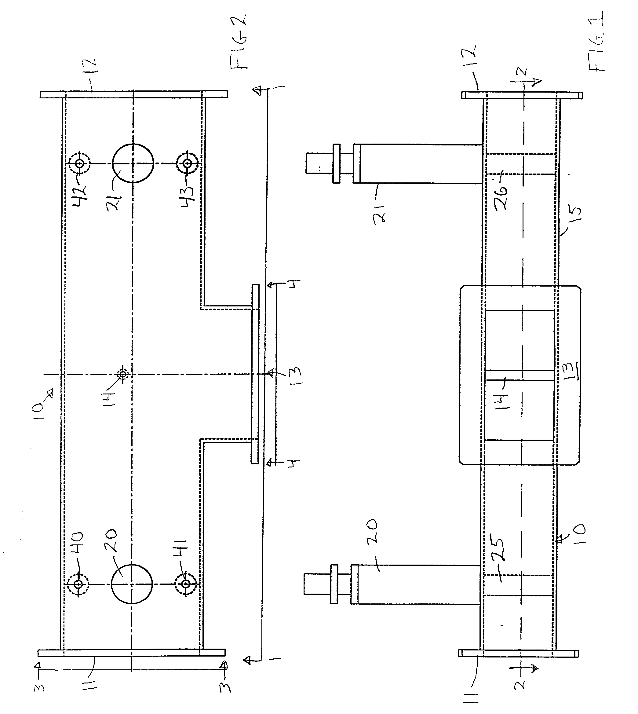
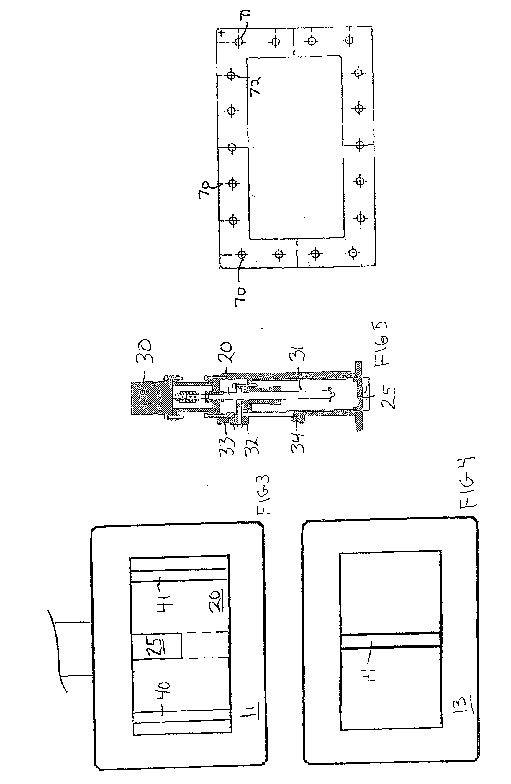
[0006] In the present invention, the division ratio is adjusted by selectively variable capacitance probes located in respect to one of two or more outputs and a single input 13. Preferably, a capacitance probe is utilized in each output (two disclosed). The probes accomplish the power division by the resistance they create, with a larger resistance lowering the power through its respective output. The preferred impedance distribution and matching post (impedance post) 14 facilitates the power division by providing a matching balancing function as later described. The adjustment of the preferred two probes 25, 26 further preferably are made simultaneously from an initial division ratio at initial design positioning through a differing division ratio range. This maintains overall efficiency while allowing for differing power outputs. Also, by synergistically altering the sizing and location of the various components, the respective power division ratio can be modified (for example by...


PUM


Abstract

A power divider for a waveguide between a single electromagnetic microwave generator input and two output ports, the divider including two tuner networks, each comprising a moveable capacitive probe with a pair of fixed flanking inductive posts.

Description

[0001] This invention relates to a compact, high power continuously variable power divider network or system for Radio Frequency ("RF"), microwave, or other high energy electromagnetic treatment systems (microwave).[0002] High Power microwave and radio frequency networks are used to provide energy for heating, curing, sterilizing, cooking, medical imaging, medical therapy, plasma generating, and other processing of substrates or treated media. The goal for such processing is to optimize the process. This processing can include multiple locations for a single generator, thus requiring some sort of power division. This typically means utilizing the minimum amount of energy to completely process two or more substrates from a single electromagnetic source in an efficient manner while, at the same time, greatly enhancing the quality and yield of the final product. The applications are primarily high power microwave and / or radio frequency energy utilization including the engineered wood i...

Claims


Application Information

Patent Timeline
IPC IPC(8): H01P5/19
CPCH01P5/19H01P5/181
Inventor HARRIS, GEORGE M.
Owner RF TECH A FERRITE
Why Eureka
Try Eureka