Sonar-controlled apparatus for the delivery of electromagnetic radiation

Inactive Publication Date: 2002-12-12
NEUROSCI TOOLWORKS
View PDF0 Cites 28 Cited by
  • Summary
  • Abstract
  • Description
  • Claims
  • Application Information

AI Technical Summary

Problems solved by technology

This is an unmistakable end-point with the HBD, a sudden and brisk sensa

Method used


Image

  • Sonar-controlled apparatus for the delivery of electromagnetic radiation
  • Sonar-controlled apparatus for the delivery of electromagnetic radiation
  • Sonar-controlled apparatus for the delivery of electromagnetic radiation

Examples


example 1

Feedback Control Procedure

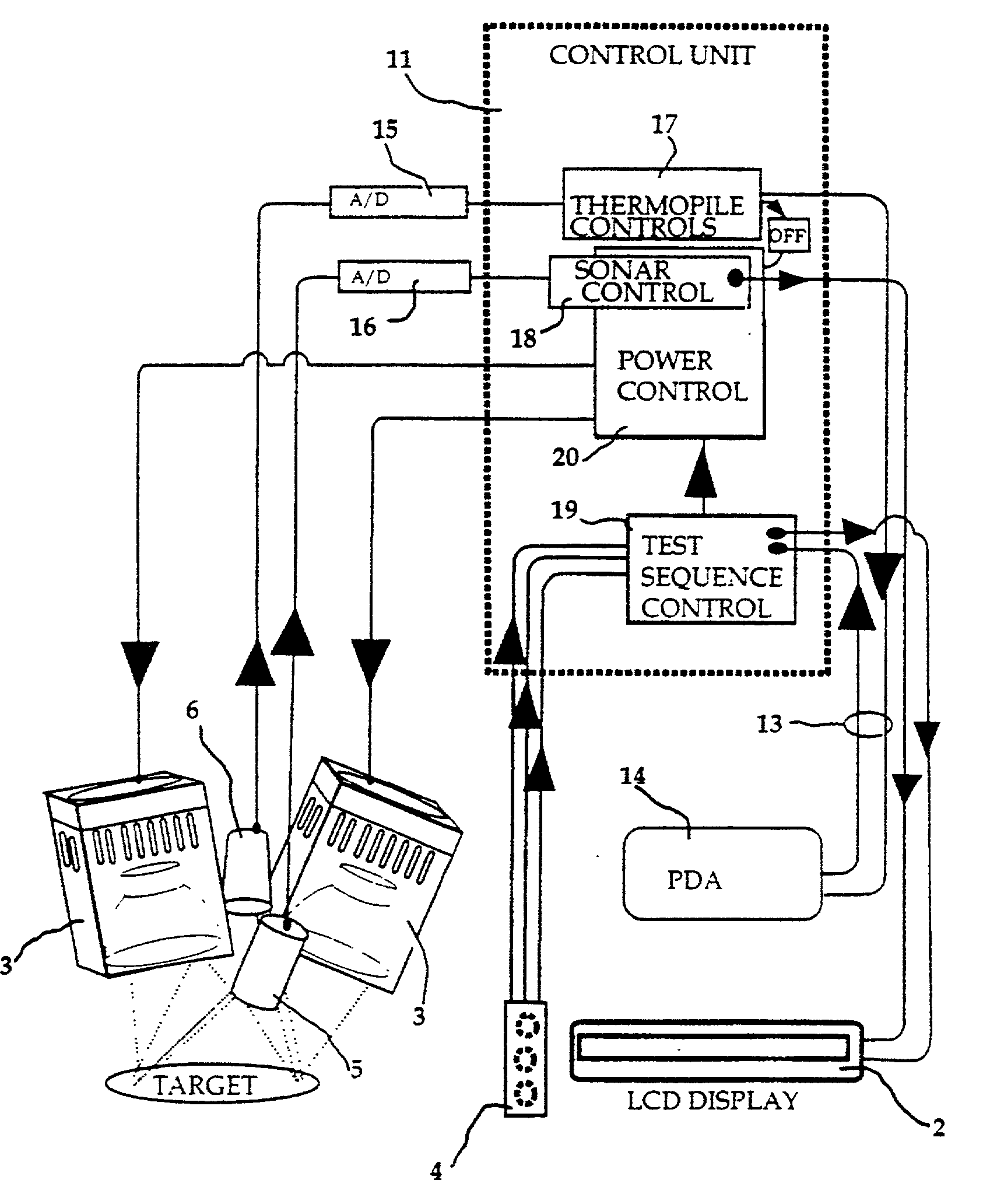
[0068] Demonstrated in the present example, a preferred embodiment provides a stable stimulus temperature at the target site and counters the effect of the tendency of a hand-held unit to move or change position under operator control upon the emission received by a target. The device achieves this automatic compensation for the effect of distance change by means of a look-up table procedure in the power control software. The process, illustrated in the flow diagram FIG. 4, was investigated using an optical bench apparatus.

[0069] Thus, regardless of tremor in the hand of the operator, the effect of the stimulus beam on target temperature is held substantially constant--at the value previously defined as producing the nominal temperature at the nominal distance of the arm-mounted version regardless of distance (within limits). Should the operator attempt to use the device outside of these limits the sonar will disengage the power to the beams, as a safety me...


PUM


Abstract

The present invention comprises devices and methods that deliver electromagnetic radiation (EMR) from an emitter to a target and employ a laser or sonar (a sensing method) to measure distance between target and EMR emitter and automatically signal the emitter control circuitry to vary either the position or the power output of the emitter (as appropriate) in order to ensure that the effect of any change in distance on the energy incident to the target is compensated rapidly and automatically. In a preferred embodiment, the device is a hand-held, non-contact heatbeam dolorimeter.

Description

[0002] The invention relates to devices that use sonar to automatically control the delivery of electromagnetic radiation, including heat and light, to a target. In a preferred embodiment, the invention relates to sonar control of the delivery of radiant heat to the skin for the measurement of pain tolerance limits.[0003] In applications where electromagnetic radiation (EMR) projected from an emitter is directed at a target, under conditions where distance may undesirably change between emitter and target, there is a need for automatic control processes that regulate the delivery rate of the EMR received at the target by adjusting the output of the emitter mechanism, the projector of heat or light or other EMR.[0004] A true feedback mechanism would use a sensor, positioned at or within the target, to feedback-control either the power output or position--the emitter-target distance--of the emitter, thus ensuring that these characteristics of the emitter are rapidly and automatically ...

Claims


Application Information

Patent Timeline
IPC IPC(8): A61B3/00A61B5/103A61B17/00A61B18/20A61B19/00A61C1/00A61F17/00A61N5/06G01S15/02G01S15/88G01S17/08
CPCA61B5/4824A61B5/483A61B18/20A61B2017/00106G01S15/88A61B2019/461A61N5/0616A61N2005/0644G01S15/025A61B2018/00636A61B2090/061G01S15/86
Inventor LIPMAN, JONATHON
Owner NEUROSCI TOOLWORKS
Why Eureka
Try Eureka