Stepped downcomer apparatus and vapor-liquid contact apparatus with same

a technology of stepping downcomer and vapor liquid contact, which is applied in the direction of combustion air/fuel air treatment, carburettant air, separation process, etc., can solve the problems of limiting the capacity of the tray, affecting the performance of the tray, and the design of the truncated downcomer has some inherent limitations, so as to maximize the active bubbling area and maximize the available downcomer length , the effect of enhancing the structural support of the tray and the down

Inactive Publication Date: 2002-12-19
SULZER MANAGEMENT AG
View PDF0 Cites 16 Cited by
  • Summary
  • Abstract
  • Description
  • Claims
  • Application Information

AI Technical Summary

Benefits of technology

0008] Under the present invention, a downcomer is provided that is designed to maximize the active bubbling area available and maintain the maximum downcomer length available for separation of the vapor-liquid mixture in the downcomer, while also providing uniform liquid flow distribution at the inlet edge of the active bubbling area. The downcomer of the present invention is also designed to enhance tray and downcomer structural support.

Problems solved by technology

However truncated downcomer designs have some inherent limitations.
The design requires a dynamic seal where the pressure drop of the liquid leaving the floor apertures prevents vapor from flowing up the downcomer from the tray below adversely affecting the tray performance.
With some liquid / gas mixtures, the truncated design may not provide sufficient downcomer length causing the fluid in the downcomer to back up onto the tray above, thus limiting the tray capacity.
The floor orifices in truncated downcomers are susceptible to plugging from particulate matter in systems where solids are present in the operating fluids.
Also, the downward release of liquid from the apertured floor tends to cause the liquid to be released unevenly onto the tray deck below.
Both of these occurrences tend to reduce tray mass transfer efficiency and decrease the effective capacity of the tray.
However, these devices have only limited effectiveness within a limited range of equipment operation.
Also in prior art, sloped or small downcomer tray designs in large diameters may often do not have sufficient mechanical strength and require separate trusses or beams that would likely impede the flow of the gas-liquid mixture on the tray deck and limit capacity.

Method used


Image

  • Stepped downcomer apparatus and vapor-liquid contact apparatus with same
  • Stepped downcomer apparatus and vapor-liquid contact apparatus with same
  • Stepped downcomer apparatus and vapor-liquid contact apparatus with same

Examples


Embodiment Construction

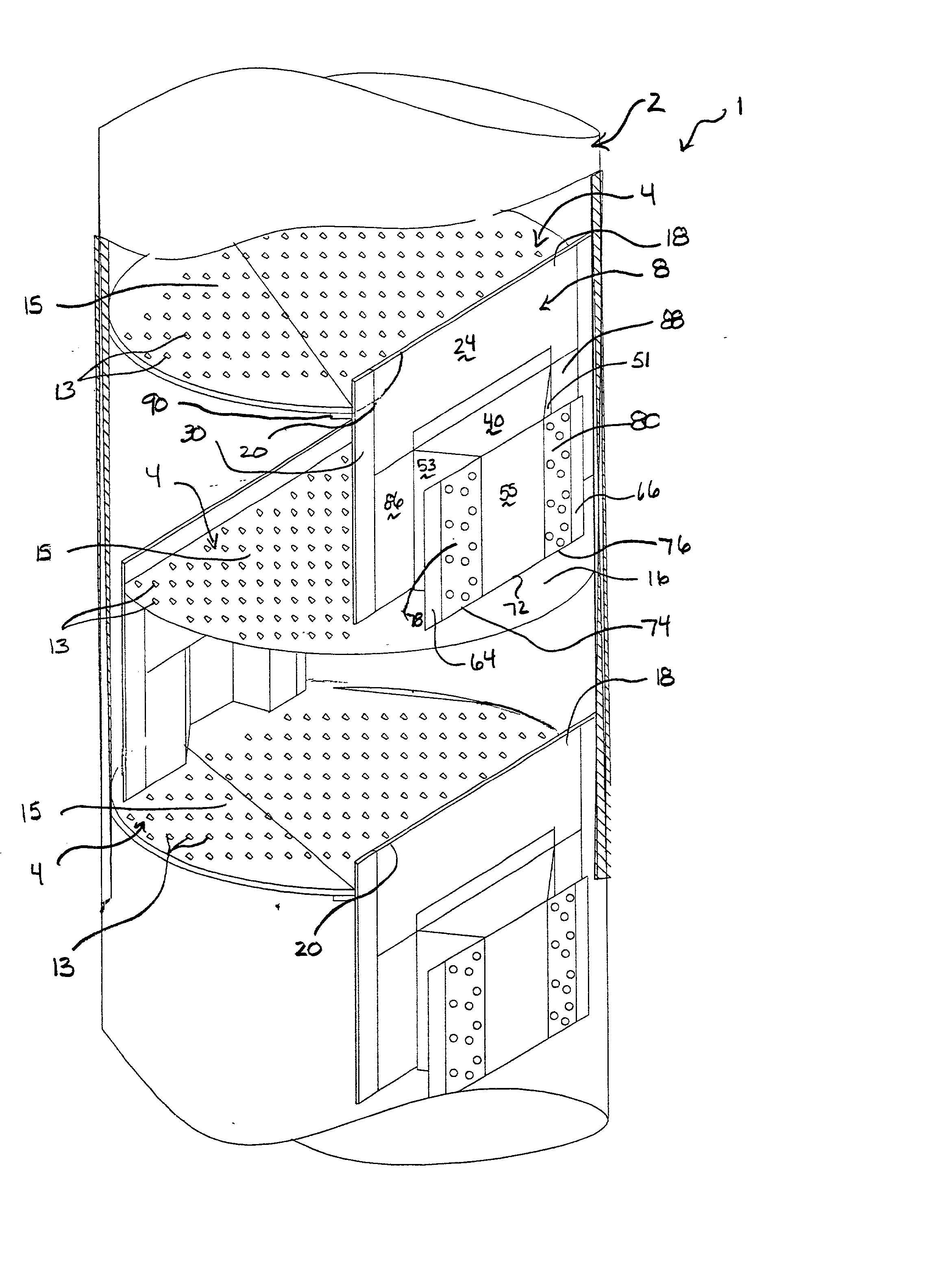
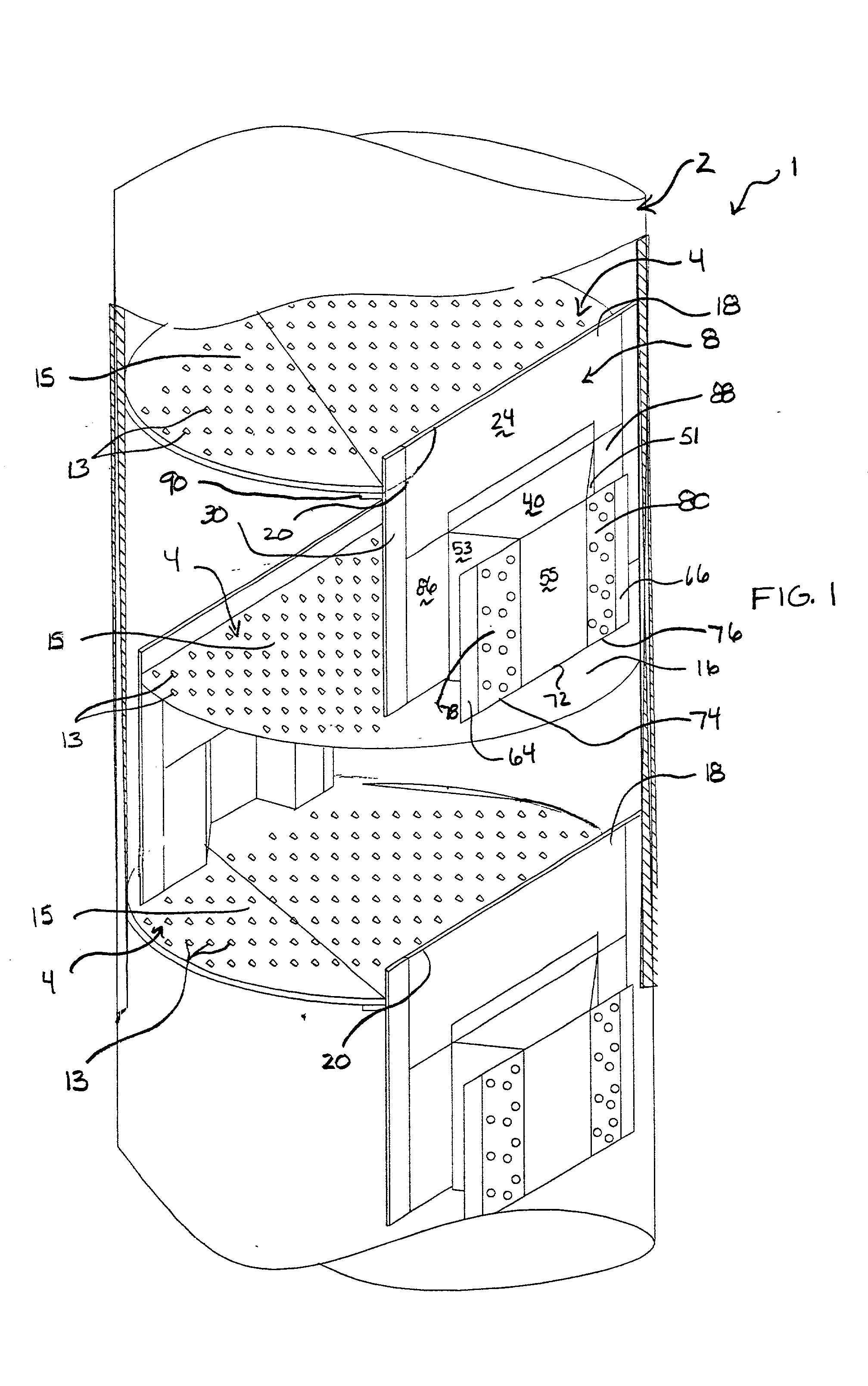
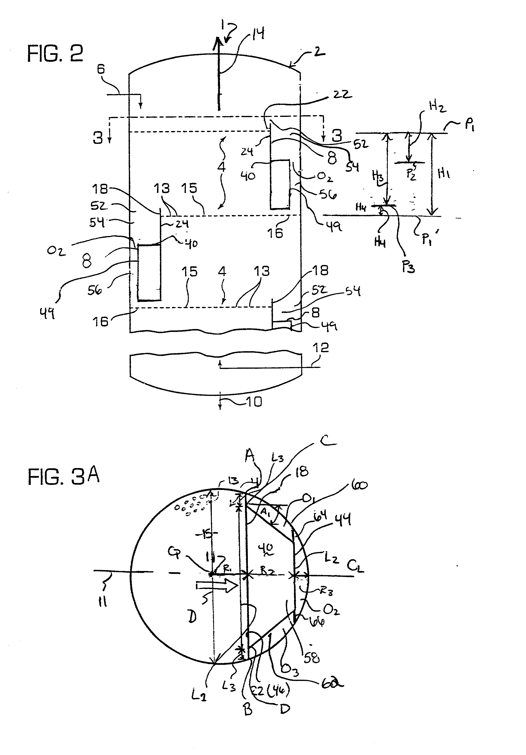
[0054] FIGS. 1 to 4B illustrate a first embodiment of a vapor-liquid contact apparatus with stepped downcomer apparatus. As shown in FIGS. 1 and 2, in particular, vapor-liquid contact apparatus 1 includes vessel 2 containing a plurality of vertically spaced horizontal contact trays 4 for supporting a vapor-liquid mixture. Liquid is introduced to the uppermost tray in the vessel by a supply line 6 (FIG. 2), it flows horizontally across the trays 4, (and) vertically (and horizontally again via a step as described below) though stepped downcomer apparatus 8, and then horizontally along the inlet portion of the tray and below a vertical opening defined between the lower edge of the downcomer and tray below. This is repeated until the liquid is discharged from the vessel by a liquid outlet line 10. The central flow axis of the vapor-liquid mixture across a tray is identified by the reference numeral 11 in FIG. 3A. As shown by FIGS. 2 and 6, for instance, air or another gas applicable to ...


PUM


Abstract

A stepped downcomer apparatus for use in a vapor-liquid contact apparatus having an intermediate level step platform with a preferred tri-edge peripheral edge and corresponding step panels extending down from that edge to form a sealing step panel wall. As a preferred support device, extensions extend in chordal fashion out from the interior vertical edge of the opposite side step wall panels and either directly or indirectly by way of support bars into a supporting relationship with a tower of the vapor-liquid contact apparatus. A main panel extends up from the interior edge of the platform and up to the above positioned tray. A weir may extend above the above positioned tray that is an extension of the main panel. This main panel is attached to the support bars and supports the step platform and walls and extensions either alone or with added support members. A tray support ledge extends inwardly from the downcomer to provide support to the upper tray. The liquid-vapor mix contacts the step platform after passing over the weir, and off from which fluid travels both along the central axis of flow and obliquely off the opposite side panels. At opposite ends of the weir, the liquid flows directly into contact with the inlet region of the lower tray, by-passing the platform. The opposite side panel walls can slope outward to vary the downcomer lower pass through volume. An embodiment features chordal wing extensions with pressure equalization openings that extends out from opposite sides of the step wall panel also into a support relationship with the tower. The lower edge of the panels of the wall and the lower edge of the extensions control the flow of fluid as it travels under the lower edging from the inlet side of the downcomer apparatus to the active area of the tray. The relative level of the lower edges can be varied to suit the intended use. Additional or replacement downcomer structural supports include vertical support members extending from a step panel to a lower tray either in the form of support brackets or tiplet extensions.

Description

FIELD OF THE INVENTION[0001] This invention relates to a downcomer apparatus and to a vapor-liquid contact apparatus provided with the downcomer apparatus, and preferably to a chemical processing vapor-liquid contact apparatus in which a vessel contains a plurality of substantially horizontal trays which support a vapor-liquid mixture. Liquid is introduced at the upper end of the vessel and it flows down from tray-to-tray, via a plurality of stepped downcomer apparatus, and the trays are apertured to provide bubbling areas through which ascending vapors can rise to contact liquid and / or vapor-liquid mixtures which are supported on and flowing across the trays.BACKGROUND OF THE INVENTION[0002] It has been recognized in the art that the performance of a contact tray apparatus can be enhanced if the liquid flow on the tray is uniform in the respect that the flow in the lateral areas of the tray is substantially the same as the flow along the central flow axis thereof. Heretofore, shape...

Claims


Application Information

Patent Timeline
Patent Type & Authority Applications(United States)
IPC IPC(8): B01D3/18B01D3/20B01D3/22
CPCB01D3/22B01D3/20
Inventor NUTTER, DALE E.PILLING, MARK W.CAMPBELL, CHRISTINA J.
Owner SULZER MANAGEMENT AG
Why Eureka
Try Eureka