Diode array end pumped slab laser

Inactive Publication Date: 2002-12-19
UNITED STATES OF AMERICA
View PDF3 Cites 7 Cited by
  • Summary
  • Abstract
  • Description
  • Claims
  • Application Information

AI Technical Summary

Problems solved by technology

Current lasers used in rangefinders are either low repetition rate or too expensive for many applications.
Diode pumped solid lasers lead to more efficient operation and therefore can be smaller and lightweight, but often do not operate over environmental temperature ranges without inefficient and cumbersome temperature control.
Previously designed diode pumped solid state lasers have used transverse pumping techniques which are effective, but require temperature control and are less efficient than desire

Method used


Image

  • Diode array end pumped slab laser
  • Diode array end pumped slab laser

Examples


Embodiment Construction

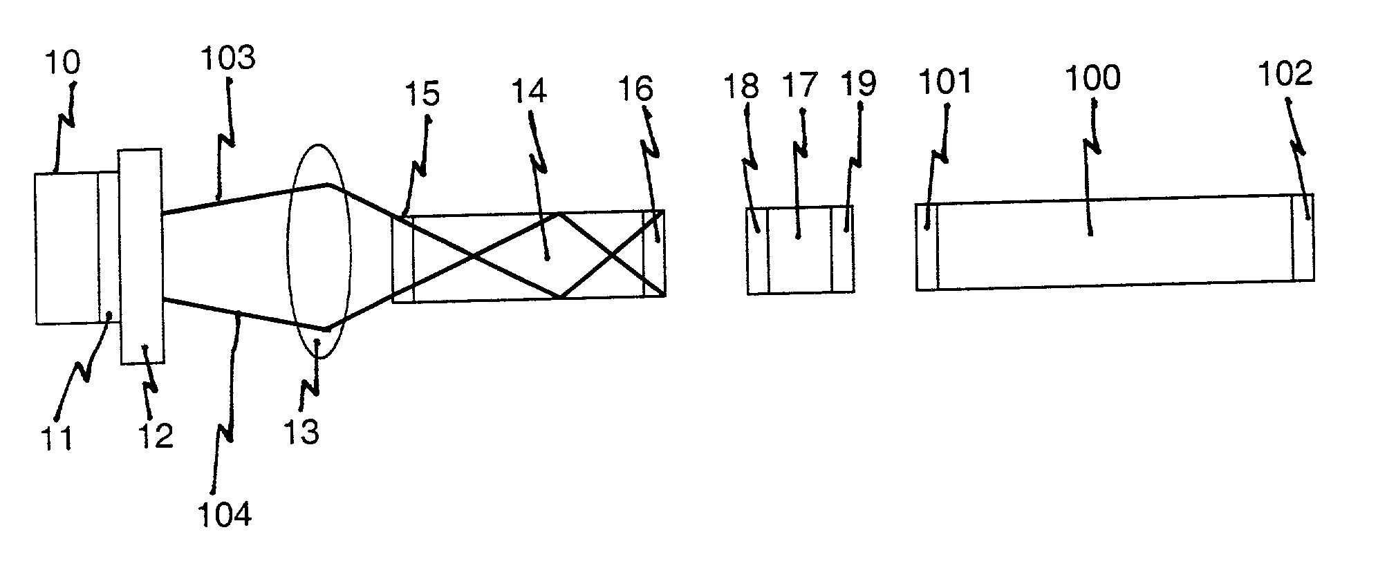
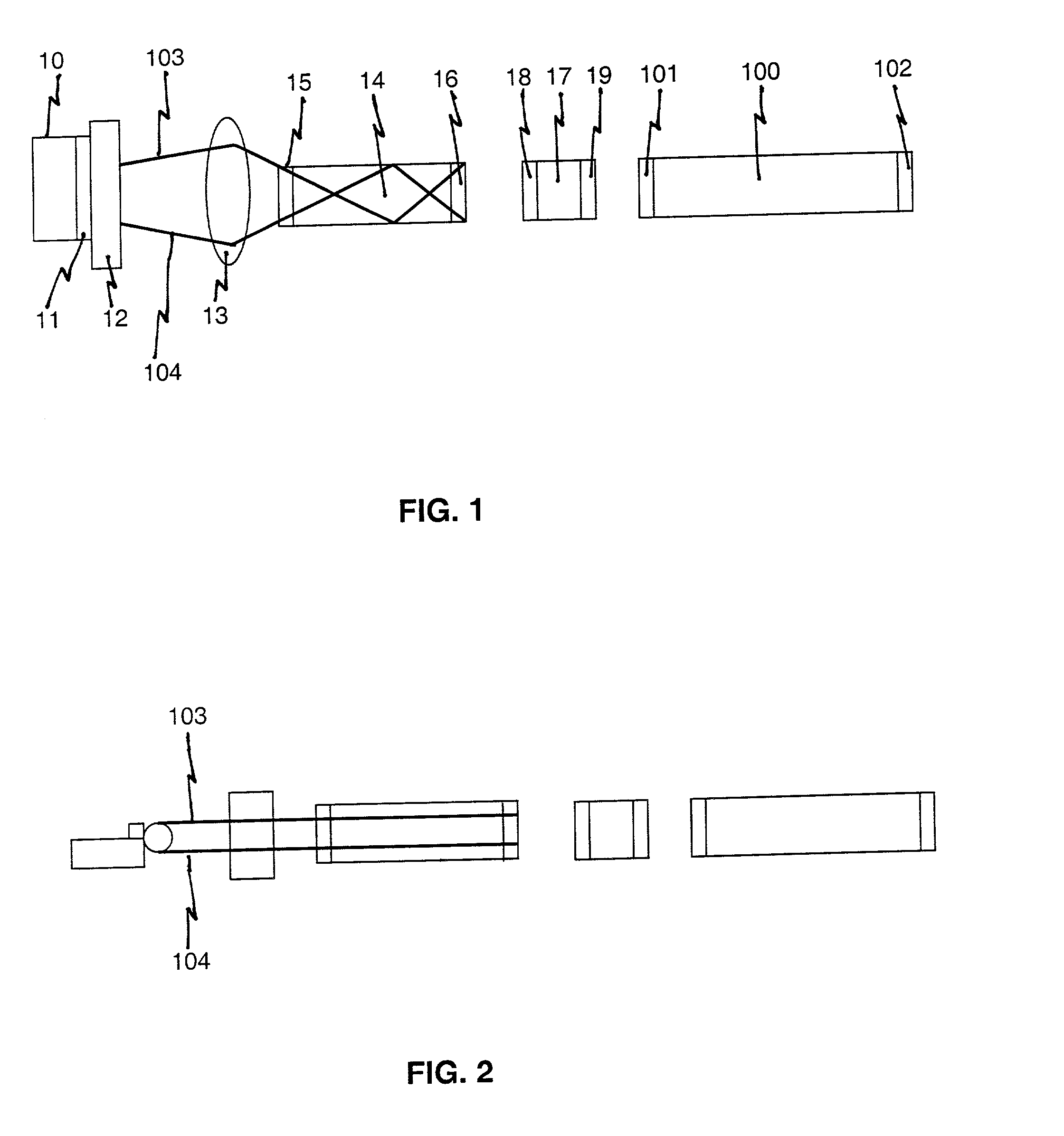
[0011] Referring now to the drawings, and more particularly to FIG. 1, there is shown a top cross-sectional view of the diode array end pumped slab laser. Laser diode 10 includes bar 11 with first lens 12 and a second cylindrical optic 13. A laser diode bar is known in the art as a linear diode array containing multiple emitters. Rectangular solid state laser crystal 14 with dichroic coatings 15 and 16, an optional intercavity 0-switch 17 with dichroic coatings 18 and 19, and an optional OPO 100 with dichroic coatings 101 and 102. A passive or active Q-switch can be placed in a laser cavity for producing short, high peak power pulses. Second cylindrical lens 13 perpendicular to the first lens collects the light in the horizontal direction and focuses the light into slab 14. Pump light 103 and 104 is trapped in the horizontal plane, as shown in FIG. 2, through total internal reflection and bounces between the polished sides of the slab while being absorbed by the active laser ion in ...


PUM


Abstract

A diode pumped solid state laser using a laser diode bar or a stack of bars with cylindrical lenses is used to end pump a rectangular cross section solid state laser slab. The combination of lenses and polished slab surfaces provides overlap of the pump light with the laser mode combined with sufficient length of material to absorb all of the pump light to produce a compact, efficient laser source.

Description

[0001] 1. Field of the Invention[0002] The present invention generally relates to diode lasers and more specifically, to end pump configurations and techniques for diode array end pumped slab lasers.[0003] 2. Description of Prior Art[0004] Current lasers used in rangefinders are either low repetition rate or too expensive for many applications. Diode pumped solid lasers lead to more efficient operation and therefore can be smaller and lightweight, but often do not operate over environmental temperature ranges without inefficient and cumbersome temperature control. Military lasers are required to be low cost, compact, and operate over a wide temperature range. Previously designed diode pumped solid state lasers have used transverse pumping techniques which are effective, but require temperature control and are less efficient than desired. Previous end pumped lasers used cylindrical rods and thus did not have efficient mode / pump overlap. Previously used flashlamp pumped solid state la...

Claims


Application Information

Patent Timeline
IPC IPC(8): H01S3/06H01S3/0941
CPCH01S3/0606H01S3/0621H01S3/0623H01S3/11H01S3/09415H01S3/1083H01S3/094084H01S3/1123
Inventor TRUSSELL, C. WARD JR.
Owner UNITED STATES OF AMERICA
Why Eureka
Try Eureka