
Intracavity sum-frequency mixing laser

a sum-frequency mixing and laser technology, applied in the direction of laser details, active medium shape and construction, electrical equipment, etc., can solve the problems of reducing manufacturing costs, difficult to achieve compact design, and large gaps near the wavelengths of 500 nm and 590 nm, so as to achieve high conversion efficiency, reduce manufacturing costs, and achieve good efficiency

Active Publication Date: 2007-03-06
KYOCERA SOC CORP
View PDF5 Cites 7 Cited by
  • Summary
  • Abstract
  • Description
  • Claims
  • Application Information

AI Technical Summary

Benefits of technology

"The present invention provides a diode-pumped solid-state laser that can produce a laser radiation at a wavelength of about 500 nm or 590 nm with minimum variation in the wavelength. The laser is designed with a common optical path for two separate laser resonators of different wavelengths and an intracavity sum-frequency mixing is conducted to obtain a laser radiation at a sum-frequency wavelength. The laser is compact and economical to manufacture. The technical effect of the invention is to provide a practical and efficient solution for generating laser radiation at specific wavelengths."

Problems solved by technology

However, there still are large gaps near the wavelengths of 500 nm and 590 nm.
Also, the fact that the optical resonator has a highly complex structure makes a compact design difficult to achieve and prevents reduction in the manufacturing cost.
However, a reflective surface that forms a part of the optical resonator is required to cause a certain amount of loss to the wavelength of 1,064 nm at which the more powerful laser radiation is produced of the two different wavelengths of the laser radiation, and this prevents a high efficiency to be achieved.

Method used


Image

  • Intracavity sum-frequency mixing laser
  • Intracavity sum-frequency mixing laser
  • Intracavity sum-frequency mixing laser

Examples


Embodiment Construction

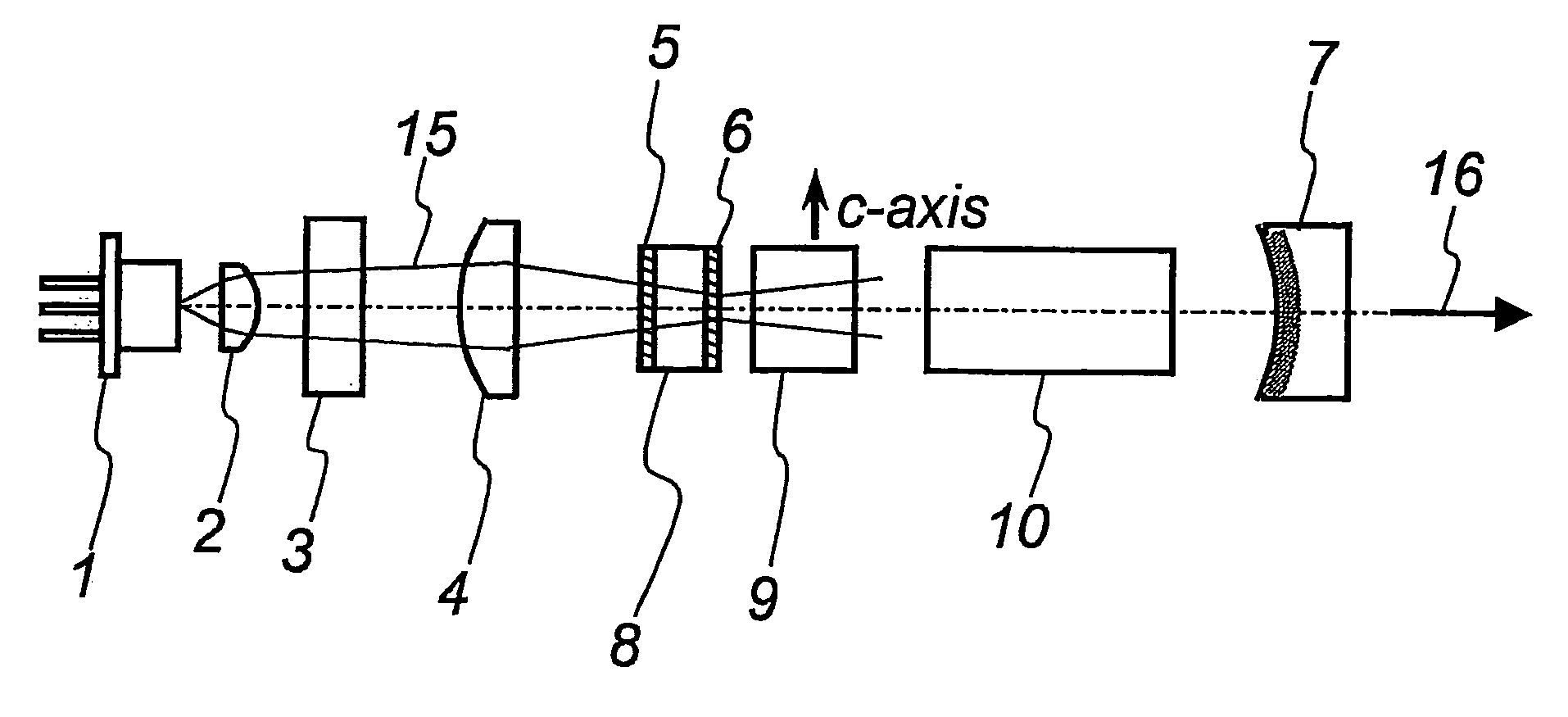
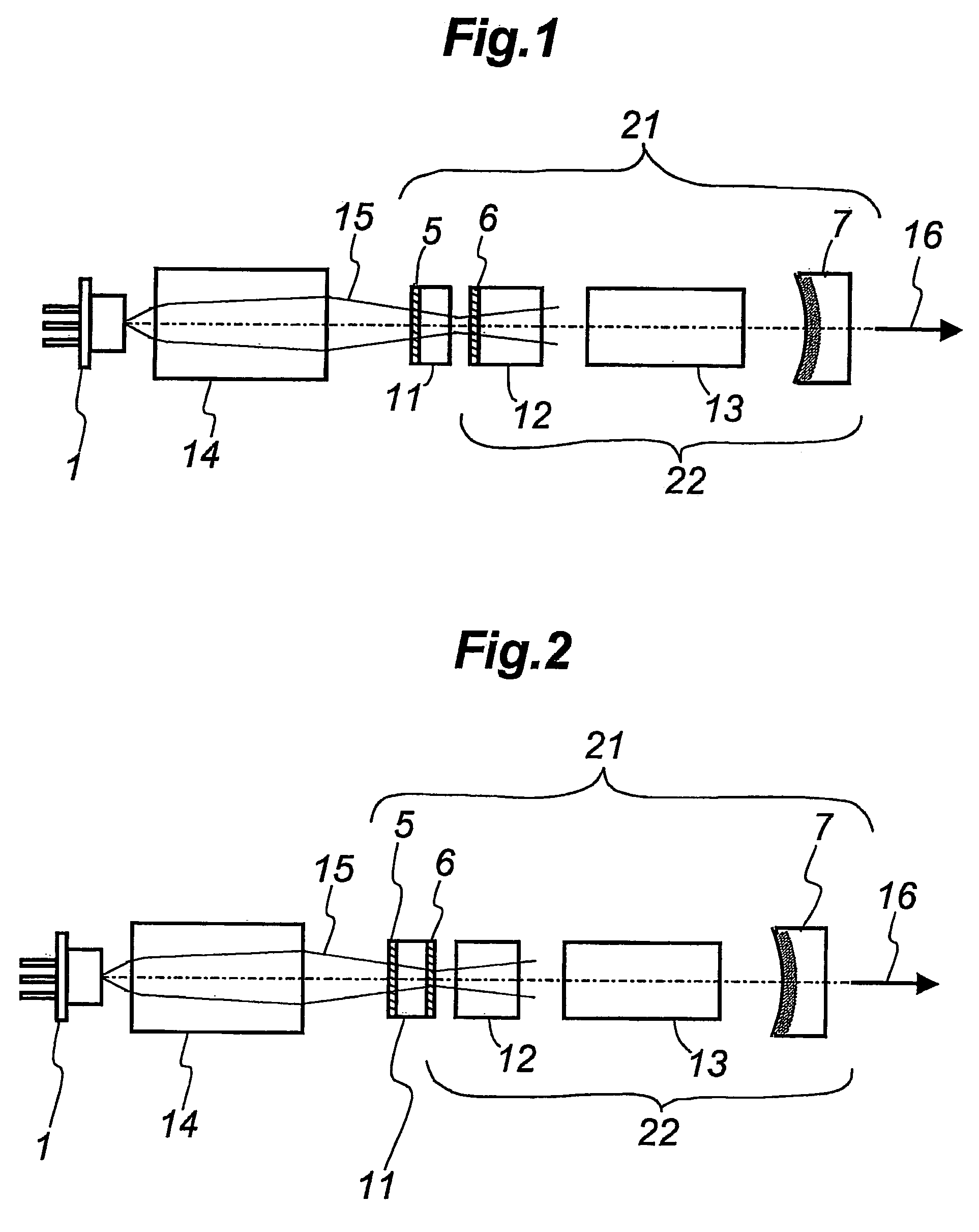
[0027]An intracavity sum-frequency mixing laser embodying the present invention is described in the following with reference to FIG. 1.

[0028]The illustrated laser include a laser optical assembly essentially consisting of a first reflective surface 5, a first laser crystal 11, a second reflective surface 6, a second laser crystal 12, a nonlinear optical crystal 13 and a third reflective surface 7, arranged in that order along a common optical axial line which is straight in the illustrated embodiment.

[0029]The first reflective surface 5 may consist of a multi-layer dielectric film applied to a face of the first laser crystal 11 or may also consist of such a film applied to a separate glass or crystal plate. In the latter case, the glass or crystal plate may not necessary be attached to or placed close to the first laser crystal 11, but may be spaced from the first laser crystal 11.

[0030]The second reflective surface 6 may consist of a multi-layer dielectric film applied to a face of...


PUM


Abstract

Provided is a diode-pumped solid-state laser adapted for an intracavity sum-frequency mixing for generating a laser radiation of a visible wavelength range by performing a sum-frequency mixing of two laser inputs in a laser resonant cavity. A pair of laser resonators of two different wavelengths are formed along a common optical path and an intracavity sum-frequency mixing is conducted so as to obtain a laser radiation at a sum-frequency wavelength by placing a nonlinear optical crystal on this common optical path. By suitably selecting the properties of the reflective surfaces that form the laser resonators, a laser radiation of a relatively short wavelength range can be obtained even though the wavelength of the pumping laser beam is relatively long, and an extremely high conversion efficiency can be achieved.

Description

PRIOR APPLICATION DATA[0001]The present application claims priority from prior Japanese application 2004-243827, filed on Aug. 24, 2004, incorporated by reference in its entirety.TECHNICAL FIELD[0002]The present invention relates to a diode-pumped solid-state laser that converts the wavelength of a laser output by using a nonlinear optical crystal. In particular, the present invention relates to an intracavity sum-frequency mixing laser that generates a laser radiation of a visible wavelength range by performing a sum-frequency mixing of two laser inputs in a laser resonant cavity.BACKGROUND OF THE INVENTION[0003]The visible-light lasers of small outputs in the range of 1 mW to 100 mW have been rapidly replaced from gas lasers to laser diodes and diode-pumped solid-state lasers over the past ten years. GaInN / GaN diode lasers are preferred in the wavelength range of 400 nm to 440 nm, and AlGaInP / GaAs diode lasers are preferred in the wavelength range longer than 630 nm.[0004]As a typ...

Claims


Application Information

Patent Timeline
Patent Type & Authority Patents(United States)
IPC IPC(8): H01S3/091
CPCH01S3/07H01S3/108H01S3/0627H01S3/09415H01S3/1673H01S3/1611H01S3/1643
Inventor KADOYA, MINORU
Owner KYOCERA SOC CORP
Learn More