Wind machines

a technology which is applied in the direction of machines/engines, renewable energy generation, greenhouse gas reduction, etc., can solve the problems of reducing the efficiency and the satisfaction of placing nozzles on the windward side of wind turbines and propellers has not been satisfied

Inactive Publication Date: 2002-12-19
NEWMAN EDWIN
View PDF0 Cites 16 Cited by
  • Summary
  • Abstract
  • Description
  • Claims
  • Application Information

AI Technical Summary

Benefits of technology

0005] The present invention avoids this problem by placing an air reaction turbine concentrically around the outside wall of the throat of the nozzle. Maximum pressure of the turbine is one atmosphere. The exhaust air

Problems solved by technology

Nozzles convert pressure energy of the wind into useable kinetic energy but placing nozzles to the windward side of wind turbines and propellers has not proved satisfying.
This plac

Method used


Image

  • Wind machines
  • Wind machines
  • Wind machines

Examples


first preferred embodiment

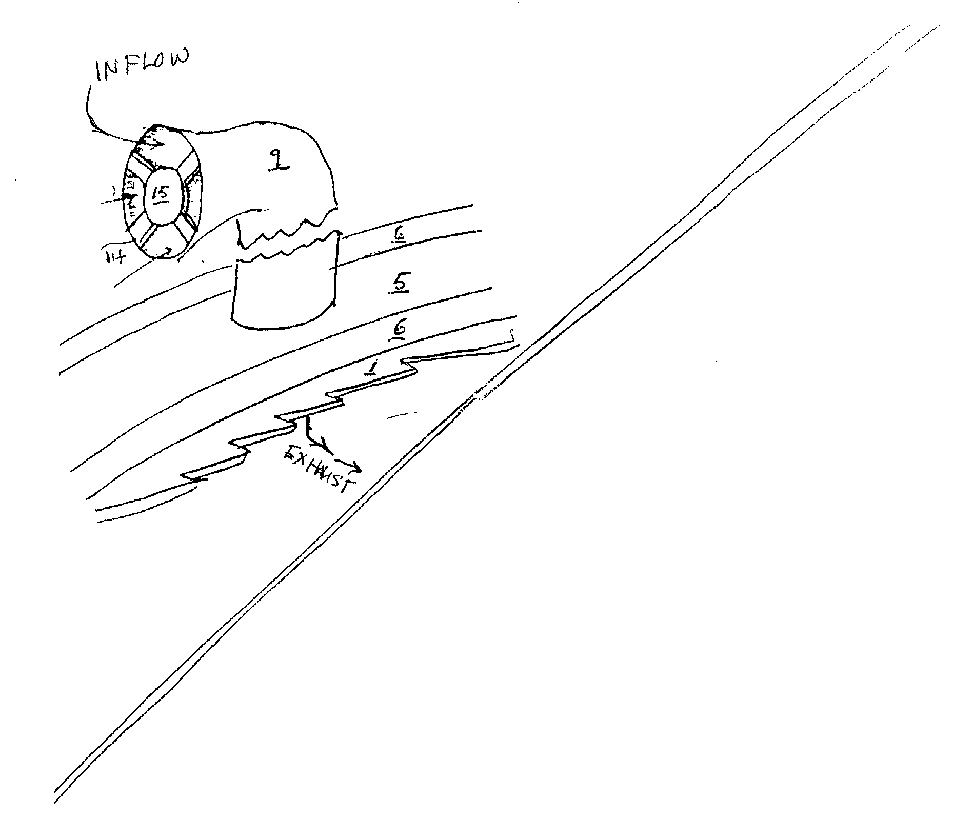
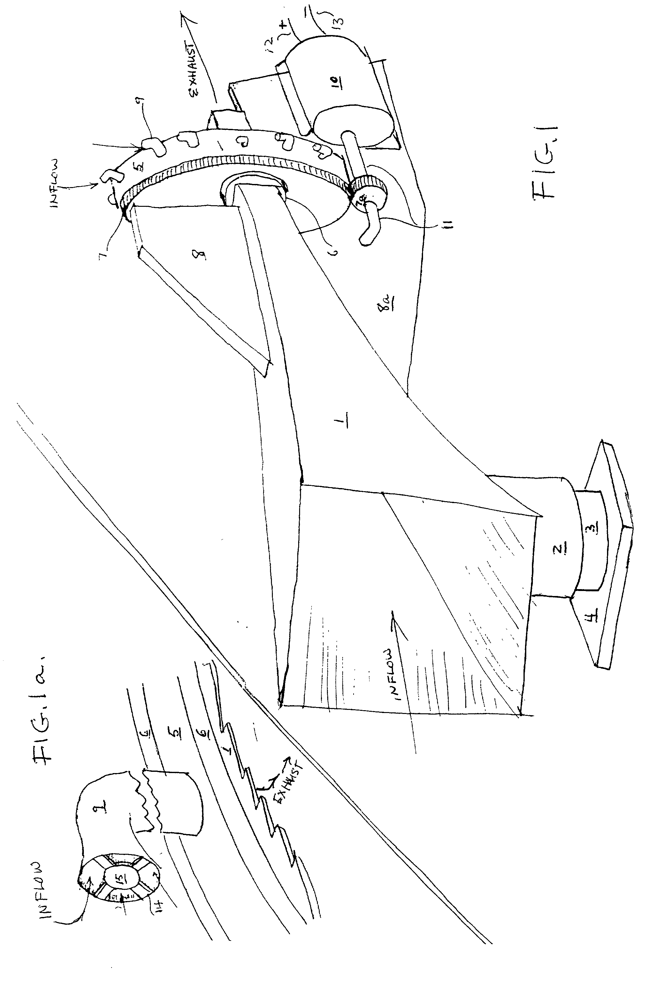
[0014] Turning to FIG. 1 there is shown a nozzle 1 mounted on a telescopic tube 2, 3 affixed to a base 4. Between sections 2 and 3 are thrust bearings (not shown) so nozzle 1 may revolve about tube section 3. Around the throat of nozzle 1 is disposed a turbine 5. In FIG. 1a there is shown thrust bearing 6 attached fixedly to both turbine 5 and nozzle 1. Turbine inflow pipe 9 is bent so the end is normal to the direction of rotation of turbine 5. The inflow end of inflow pipe 9 is partly covered by disc 14 fixedly attached to the rim of inflow pipe 9 by connectors 15. The outer surface of disc 14 is level with the rim of pipe 9. The area defined by pipe rim connectors 15 and disc 14 through which air flows should be at least equal to the cross-sectional area of inflow pipe 9.

[0015] Again in FIG. 1 there is shown a plurality of inflow pipes 9 disposed around the circumference of turbine 5. Fixedly attached to turbine 5 is spur gear 7 which is made to mesh with smaller spur gear 7a. No...

second preferred embodiment

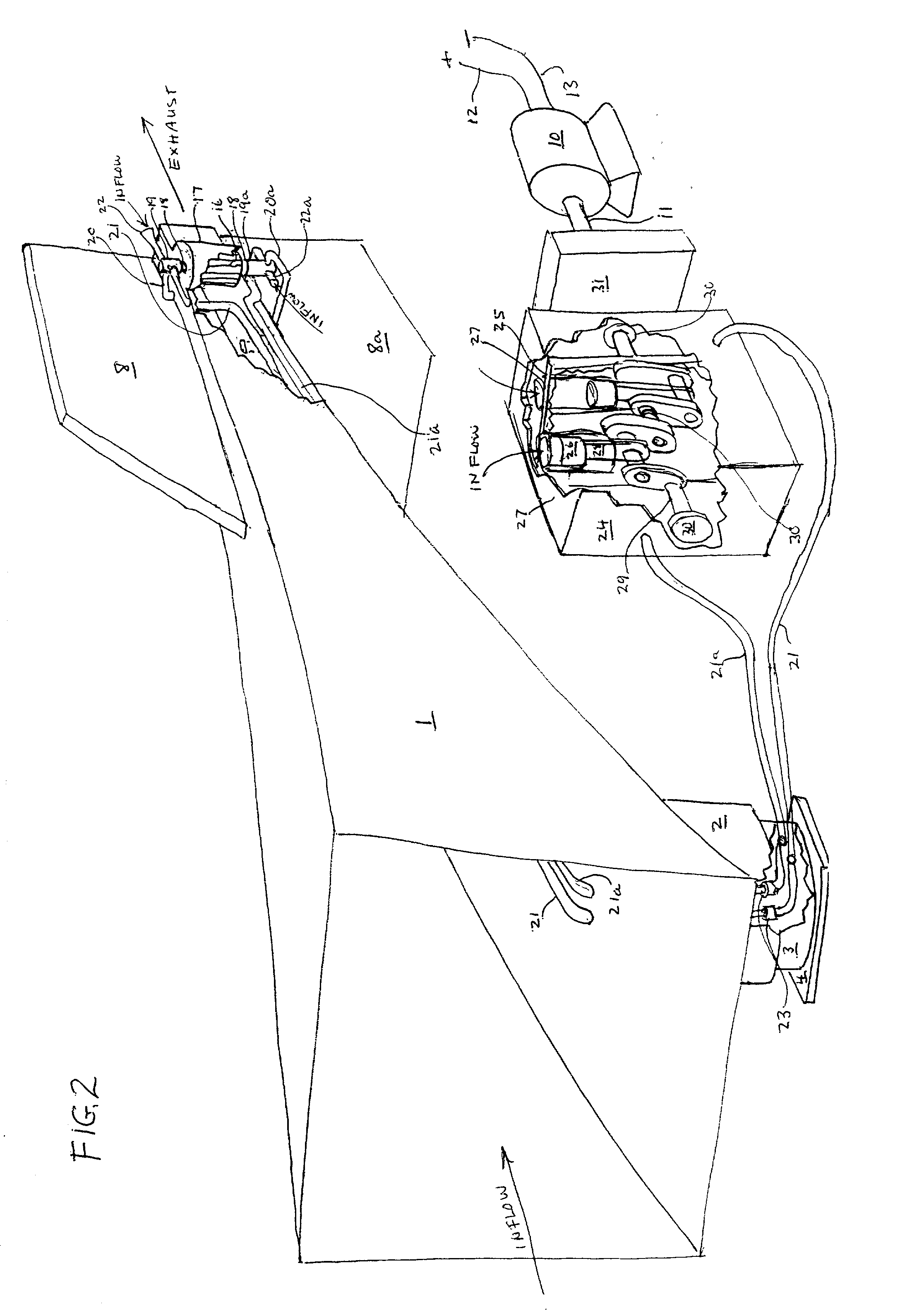
[0017] Turning to FIG. 2 there is shown a base 4. Firmly fixed to base 4 is a cylindrical tower 3. Fitting telescopically over tower 3 is a larger tower 2. which is fixedly attached to nozzle 1. As in the first preferred embodiment thrust bearings fitted between cylinders 2, 3 allow nozzle 1 to be freely rotated. Within the throat of nozzle 1 is turbine 16 within recess wall 17 and mounted on shaft 18. This is a tangential turbine whose blade tips only extend into the throat a small distance. At the ends of shaft 18 are two 3-way ball valves 19, 19a whose rotors are fixedly attached to shaft 18 and whose bodies are fixedly attached to nozzle 1. Pipes 20, 20a are passageways from the throat of nozzle 1 to an opening in the bodies of valves 19, 19a respectively. Pipes 22, 22a are passageways leading from valves 19, 19a respectively extending through rotateable gas seals 23 to the volumes on either side of wall 25 of airtight container 24. Within container 24 is crankshaft 29 mounted o...


PUM


Abstract

Wind machines are disclosed in which the pressure energy of the wind is converted into electrical energy. A nozzle unobstructed by any turbine or propeller bearing a significant load is made to face the wind. The nozzle converts the pressure energy of the wind into kinetic energy. In one embodiment a turbine is disposed around the throat of the nozzle and air sucked through the turbine and exhausted through the throat of the nozzle. An obstruction at the turbine inlets is placed in such a way as to cause a pressure variation on either side of the obstruction, causing the turbine to rotate. In a second embodiment a small turbine within the throat of the nozzle is made to revolve several three way ball valves. These valves open and close passage-ways so as to admit or evacuate air from one side of pistons in cylinders of an atmospheric engine. The low pressure in the volume of the nozzle throat serves as an energy sink. The other side of the pistons are open to the atmosphere.

Description

[0001] 1. Field of the Invention[0002] The present invention relates to the conversion of wind energy into electrical energy. In particular the invention relates to the conversion of pressure energy of the wind into electrical energy.[0003] 2. Background and Summary[0004] Wind possesses mechanical energy. The two relevant components of mechanical energy are kinetic energy and pressure energy. Up to now only the kinetic energy of the wind has been considered for conversion into electrical energy. Yet it is apparent that the pressure energy of the wind is far greater than its kinetic energy. Nozzles convert pressure energy of the wind into useable kinetic energy but placing nozzles to the windward side of wind turbines and propellers has not proved satisfying. In great variety such U.S. Patents such as Jander, U.S. Pat. No. 1,209,301, Sellman U.S. Pat. No. 3,986,786, Hope et al. U.S. Pat. No. 4,088,419, Bergstein U.S. Pat. No. 4,960,363 and Les Strange U.S. Pat. No. 6,043,565 show tur...

Claims


Application Information

Patent Timeline
IPC IPC(8): F03D1/04F03D3/04F03D5/00
CPCF03D1/04F03D3/0427Y02E10/74Y02E10/70Y02E10/72F03D5/00F03D9/25F03D15/10
Inventor NEWMAN, EDWIN
Owner NEWMAN EDWIN
Why Eureka
Try Eureka