Control apparatus for device having dead band, and variable valve system

a control apparatus and dead band technology, applied in the direction of device details, machine/engine, device details, etc., can solve the problems of excessive response, difficult control of such a control object, and difficulty in realizing both a fast response and control stability at the same tim

Inactive Publication Date: 2003-01-02
DENSO CORP
View PDF16 Cites 37 Cited by
  • Summary
  • Abstract
  • Description
  • Claims
  • Application Information

AI Technical Summary

Problems solved by technology

In the case of a control object having a dead band, however, the response of the control object is non-linear so that it is difficult to realize both a fast response and control stability at the same time.
It is particularly hard to control such a control object in areas in close proximity to boundaries of the dead band.
With such correction, however, it is feared that an excessive response is resulted in right after a departure from the dead band.
In addition, since the apparatus utilizes engine oil, a delay time increases due to a decrease in oil pressure.
After a long stopped state of the engine or after oil replacement, however, oil is inevitably lost from an oil-pressure circuit in

Method used


Image

  • Control apparatus for device having dead band, and variable valve system
  • Control apparatus for device having dead band, and variable valve system
  • Control apparatus for device having dead band, and variable valve system

Examples


first embodiment

[0107] First Embodiment

[0108] By referring to the diagrams, the following description explains a plurality of preferred embodiments of the present invention. It is to be noted that, throughout the following description of the embodiments, an element in a specific embodiment identical with or similar to a counterpart employed in a preceding embodiment is denoted by the same reference numeral as the counterpart in the explanation of the specific embodiment and figures related to the specific embodiment, and the description of the element is not repeated.

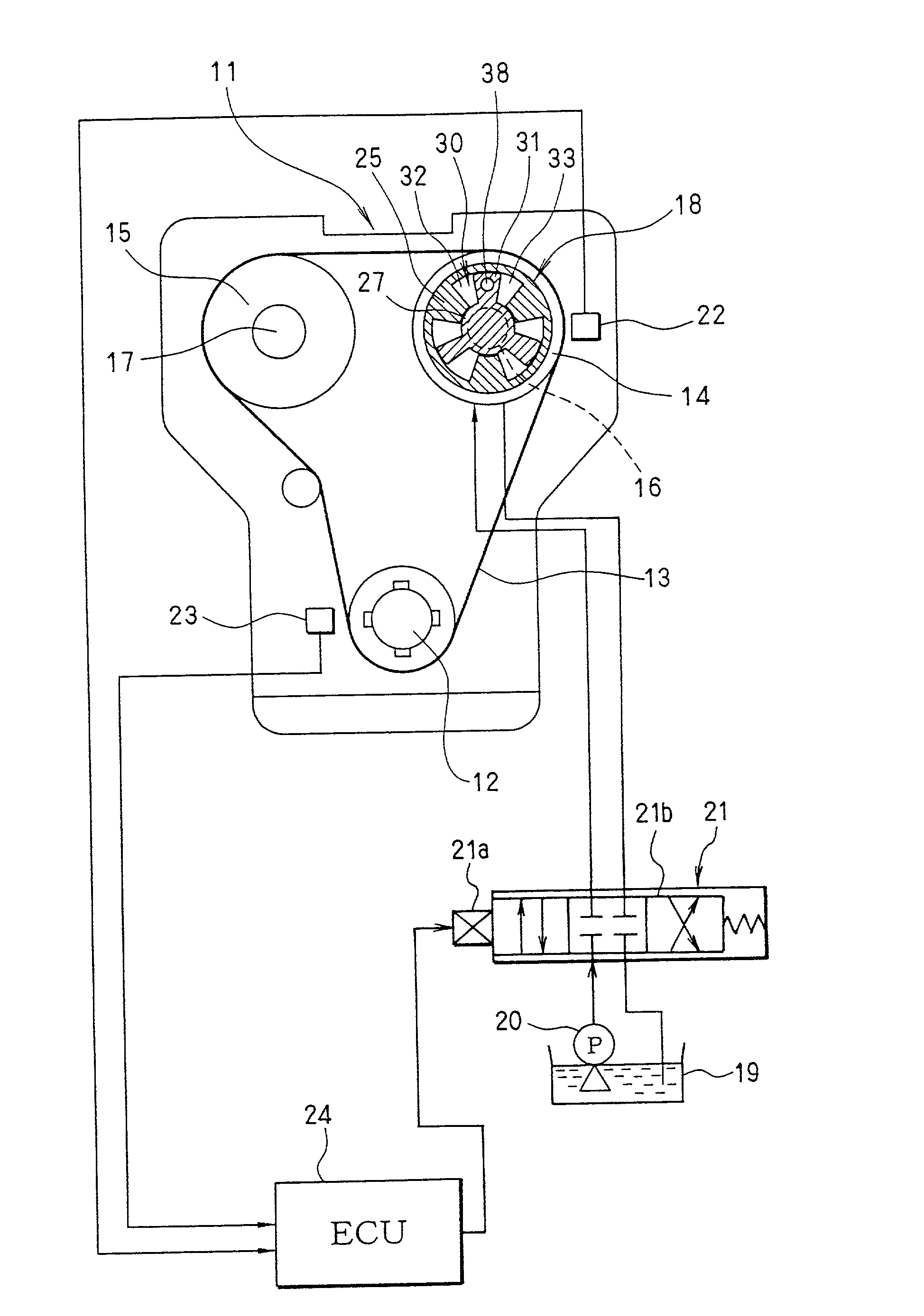
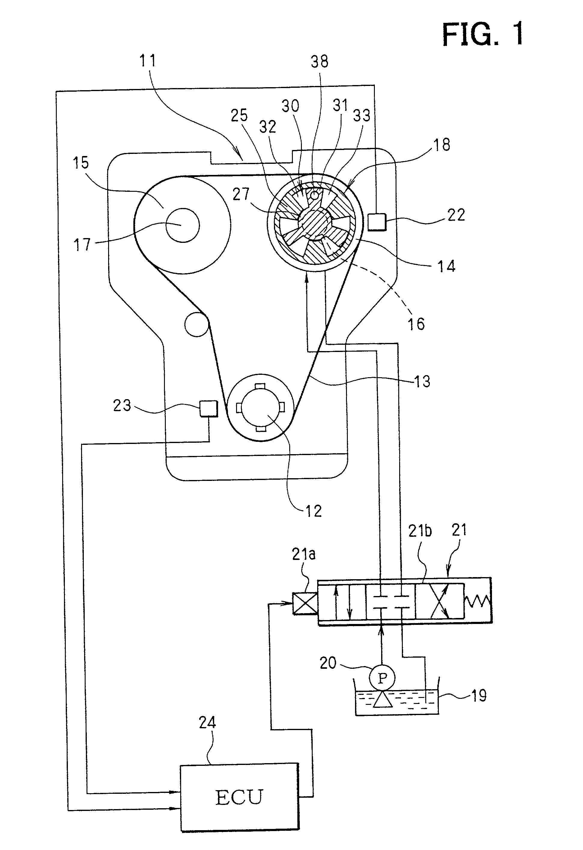
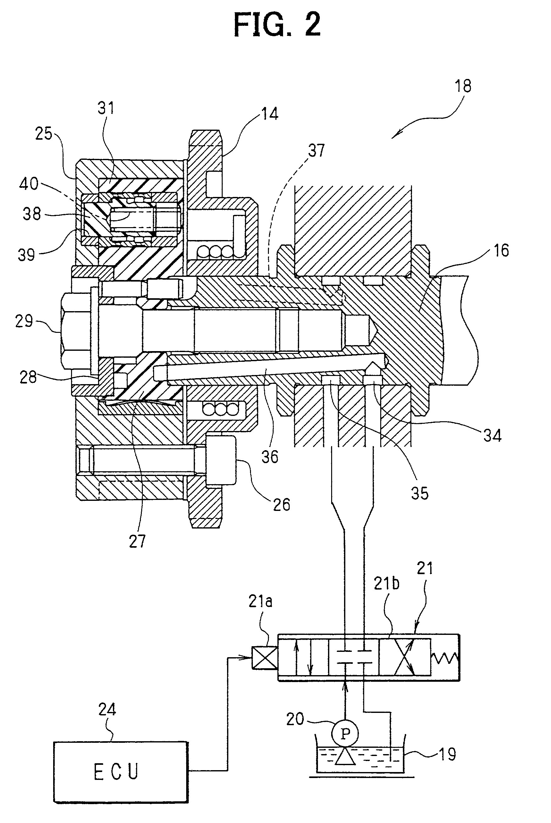
[0109] First of all, the configuration of a variable valve timing control system is explained by referring to FIGS. 1 and 2. An internal combustion engine 11, which is referred to hereafter simply as an engine 11, has an intake-side camshaft 16 and an exhaust-side camshaft 17. A crankshaft 12 is connected to sprockets 14 and 15 by a timing chain (or a timing belt) 13. A power driving the crankshaft 12 is propagated to the intake-side c...

second embodiment

[0141] Second Embodiment

[0142] Next, a second embodiment of the present invention is explained by referring to FIGS. 10 and 11. In this case, a map shown in FIG. 10 is used for finding an amplitude d that is suitable for the position of the center DCENT of the duty value Duty. As is obvious from FIG. 10, the amplitude d that is suitable for the center DCENT of the duty value Duty is a maximum value when the center DCENT of the duty value Duty is located at a position in close proximity to the holding duty value Dh or in close proximity to the center of the dead band. The longer the distance by which the position of the center DCENT of the duty value Duty is separated away from the holding duty value Dh, the smaller the amplitude d. The maximum value of the amplitude d is at least equal to half the width of the dead band. For an area outside the dead band, a good response characteristic is obtained even if the duty value Duty is not vibrated. In addition, there is an effect of avoidi...

third embodiment

[0145] Third Embodiment

[0146] In a third embodiment, when the vibration center value DCENT exists outside the dead band, the amplitude d is reset to 0 to halt the vibration of the duty value Duty. Thus, it is possible to provide a good response characteristic as well as terminate the vibration. As shown in FIG. 12, if the vibration center value DCENT goes beyond the limit of the dead band, the vibration of the duty value Duty is terminated. In order to keep up with variations in dead-band width and changes caused by an aging characteristic, the duty value Duty may be vibrated over a range slightly wider than the dead band.


PUM


Abstract

A control unit employed in a variable valve timing apparatus vibrates a control signal for controlling an oil-pressure control valve. If the vibration center of the duty value of the control signal for driving the oil-pressure control valve lies in a dead band, the vibration takes the duty value to the outside of the dead center temporarily. Thus, even if the center value of the control signal lies in the dead band, the valve timing of the oil-pressure control valve changes with variations in control signal. As a result, the width of the dead band appears small or to have a value of zero. Accordingly, the response characteristic of variations in valve timing to the variations in control signal is improved. The vibration of the control signal is also effective for detection of a width of the dead band.

Description

[0001] This application is based on Japanese Patent Applications No. 2001-182521 filed on Jun. 15, 2001, No. 2001-218091 filed on Jul. 18, 2001, No. 2002-69540 filed on Mar. 14, 2002, and No. 2002-140028 filed on May 15, 2002, the contents of which are incorporated herein by reference.[0002] 1. Field of the Invention[0003] The present invention relates to a control apparatus for a device having a dead band. In the dead band, the device is not responsive fully or substantially to an input. That is, the device has non-linear characteristics. The present invention also relates to a variable valve timing system that has a malfunction-determining means.[0004] 2. Description of Related Art[0005] A control system has a configuration for controlling a control object to a target state. In the case of a control object having a dead band, however, the response of the control object is non-linear so that it is difficult to realize both a fast response and control stability at the same time. It ...

Claims


Application Information

Patent Timeline
IPC IPC(8): F01L1/34F01L1/344
CPCF01L1/34F01L2001/3443F01L2001/34443F01L2001/34469F01L2001/34479F01L2001/34483F01L2800/00Y10T137/8242
Inventor MAJIMA, YOSHIHIROHASEGAWA, JUNIIDA, HISASHIINOUE, MASAOMIMAEJI, HIDEYUKIURUSHIHATA, HARUYUKIIWASE, NORIAKI
Owner DENSO CORP
Why Eureka
Try Eureka