

Motor control apparatus
a technology of motor control and control apparatus, which is applied in the direction of electric controllers, electronic commutators, dynamo-electric converter control, etc., can solve the problems of increasing uneven distribution, affecting the efficiency of motors, and compromising the extent to which motor efficiency is improved,
- Summary
- Abstract
- Description
- Claims
- Application Information
AI Technical Summary
Problems solved by technology
Method used
Image

Examples
first embodiment
[0034] First Embodiment
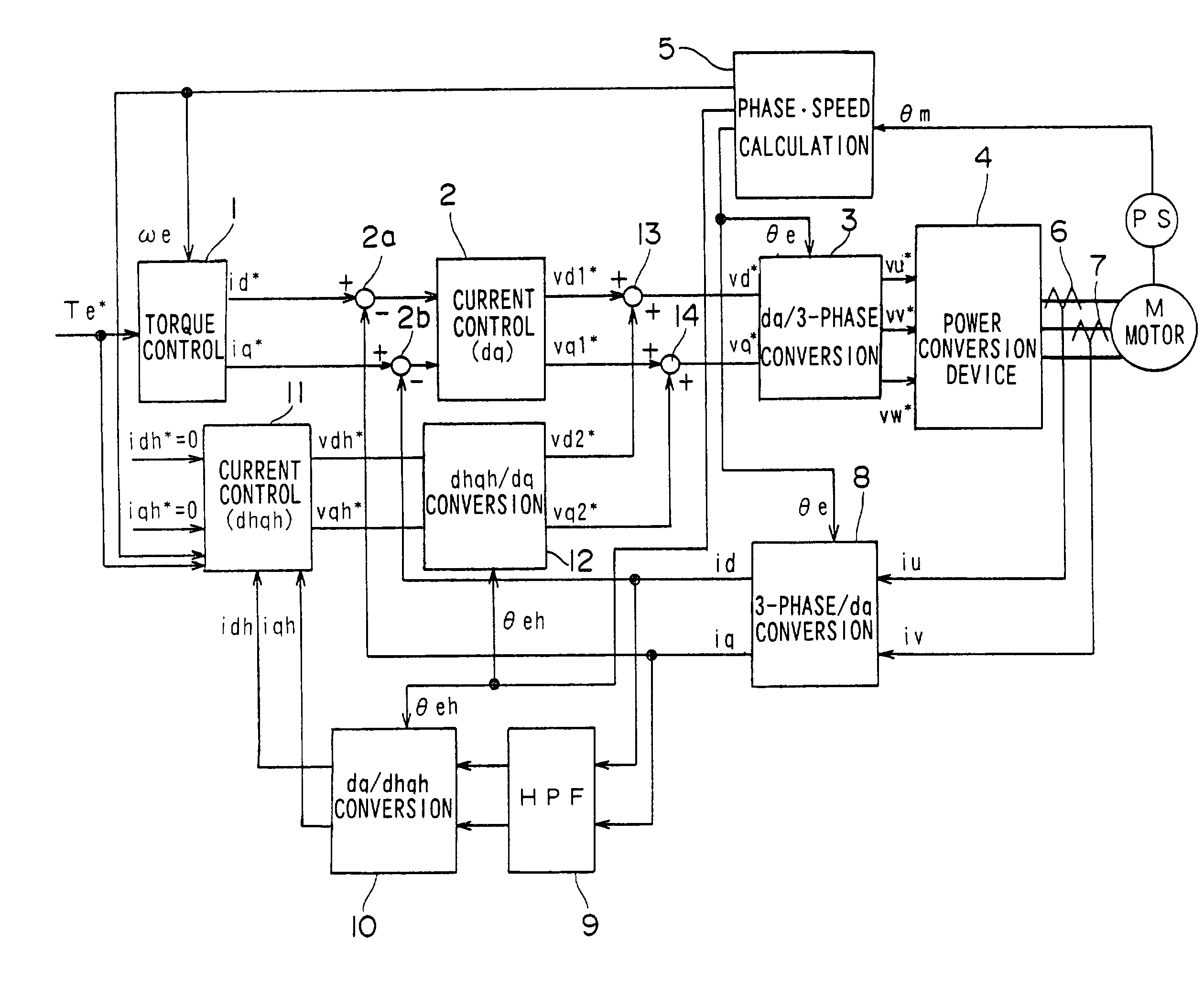
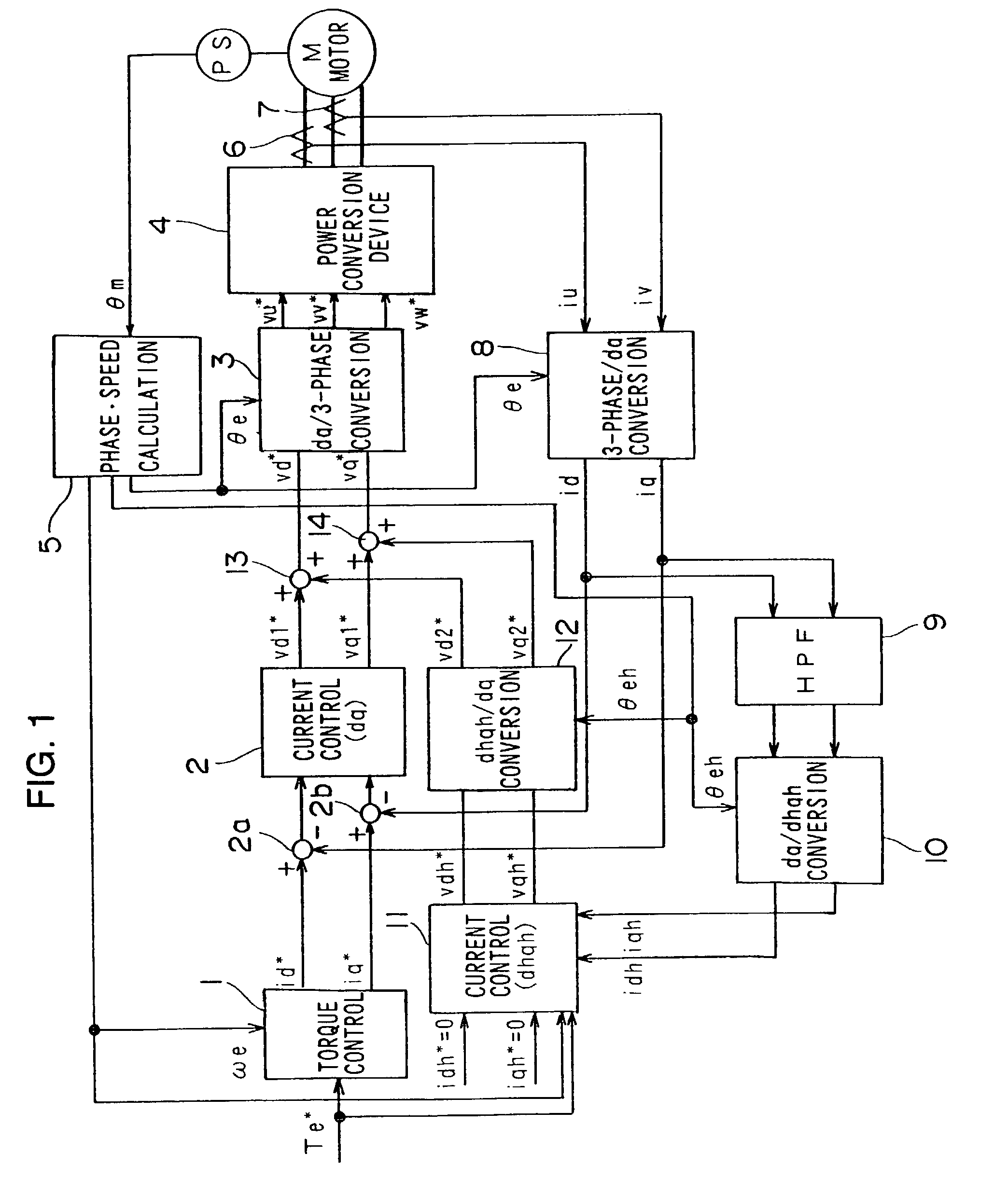
[0035] FIG. 1 shows the structure of the motor control apparatus achieved in the first embodiment. The motor control apparatus in the first embodiment, which includes a fundamental wave current control system and a higher harmonic current control system, reduces the higher harmonic current and also reduces the current distortion that occurs when the phase voltage becomes saturated. This motor control apparatus implements drive control on the 3-phase current motor through vector control.
[0036] The fundamental wave current control system is a circuit that controls primarily the fundamental wave components of 3-phase currents iu, iv and iw flowing through a 3-phase AC motor M by converting the 3-phase currents iu, iv and iw to a d-axis current component and a q-axis current component in an orthogonal coordinate system (hereafter referred to as a dq-axis coordinate system). The dq-axis coordinate system rotates in synchronization with the motor rotation and contro...
second embodiment
[0057] Second Embodiment
[0058] In the first embodiment described above, saturation of the output voltage is detected by ascertaining the output state of the motor. In the motor control apparatus achieved in the second embodiment, saturation of the output voltage is detected based upon a phase voltage command value.
[0059] FIG. 6 shows the structure of the motor control apparatus achieved in the second embodiment. It is to be noted that the same reference numerals are assigned to functional blocks having functions similar to those of control blocks shown in FIG. 1 and the following explanation focuses on the differences.
[0060] A voltage saturation judging circuit 15 judges as to whether or not the output voltage is in a saturated state based upon phase voltage command values vu*, vv* and vw* corresponding to the three phases. The structure assumed in the voltage saturation judging circuit 15 is shown in detail in FIG. 7. An absolute value circuit 41 determines the absolute values of t...
third embodiment
[0066] Third Embodiment
[0067] In the second embodiment described above, a detection is performed to ascertain whether or not the output voltage is in a saturated state based upon the 3-phase voltage command values vu*, vv* and vw*. In the motor control apparatus in the third embodiment, on the other hand, an output voltage-saturated state is detected based upon d-axis voltage command value vd1* and the q-axis voltage command value vq1*, the dh-axis voltage command value vd2* and the qh-axis voltage command value vq2*.
[0068] FIG. 9 shows the structure adopted in the motor control apparatus in the third embodiment. It is to be noted that the same reference numerals are assigned to control blocks having functions similar to those in the control block diagrams presented in FIGS. 1 and 6, and the following explanation focuses on the differences.
[0069] A voltage saturation judging circuit 15A judges as to whether or not the output voltages are in a saturated state based upon the d-axis an...
PUM
 Abstract
Description
Claims
Application Information