Methods and apparatus for I/Q imbalance compensation

a technology of imbalance compensation and equipment, applied in the field of methods and equipment, can solve the problems of phase and amplitude imbalance compensation operations, phase and error correction operations,

Inactive Publication Date: 2003-01-09
QUALCOMM INC
View PDF32 Cites 64 Cited by
  • Summary
  • Abstract
  • Description
  • Claims
  • Application Information

AI Technical Summary

Benefits of technology

0019] To obtain the desired symbol averaging effect in generation of the phase imbalance correction coefficient, in some embodiments the phase imbalance correction coefficient is generated in a manner that depends on the symb

Problems solved by technology

In some embodiments, the imbalance correction operation is limited to phase error correction.
Howev

Method used


Image

  • Methods and apparatus for I/Q imbalance compensation
  • Methods and apparatus for I/Q imbalance compensation
  • Methods and apparatus for I/Q imbalance compensation

Examples


Embodiment Construction

[0025] As mentioned earlier, the present invention describes methods and apparatus for correcting for I and Q phase imbalance in a received signal. As will be discussed below, this is done by adaptively compensating for I / Q imbalance using simple feedback in accordance with the present invention.

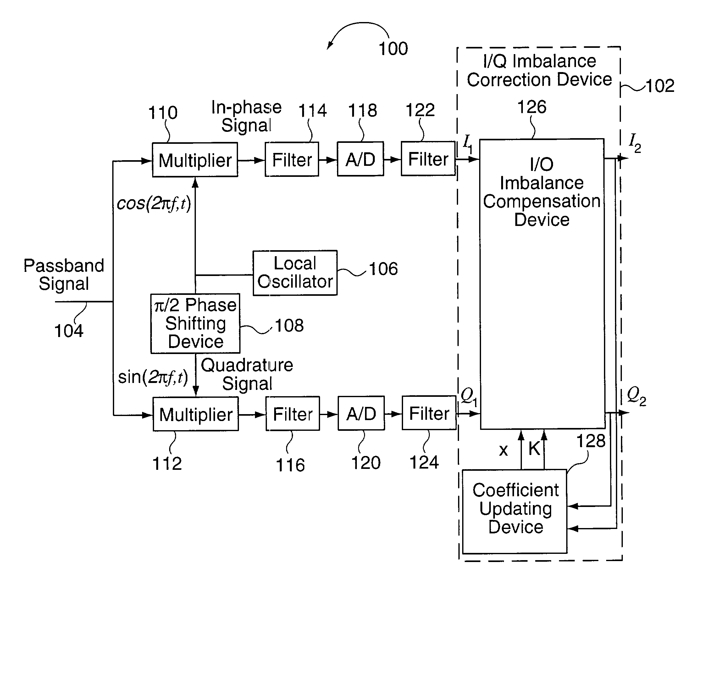
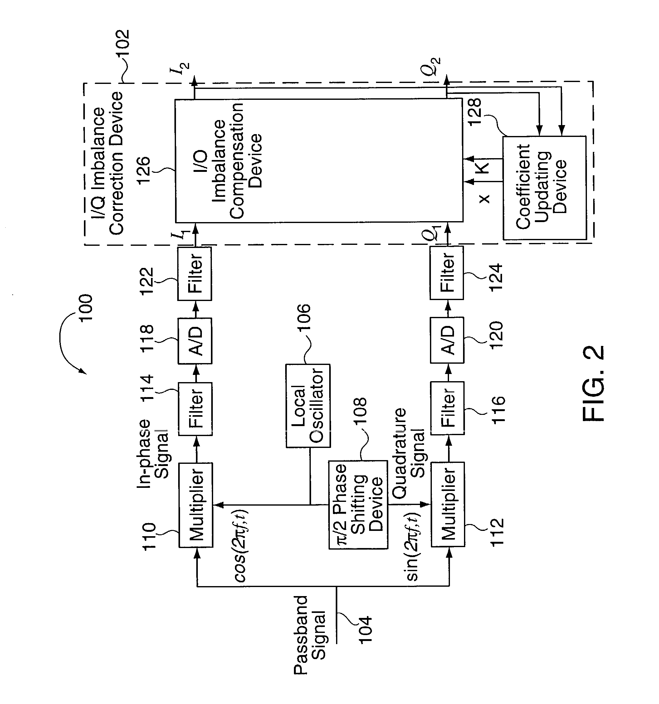
[0026] FIG. 2 illustrates an exemplary communication apparatus 100 implemented in accordance with one exemplary embodiment of the present invention. The apparatus may be, e.g., part of a receiver. The communication apparatus 100 includes an input line 104, local oscillator 106, .pi. / 2 phase shifting device 108, two multipliers 110, 112, two analog filters 114, 116, two analog to digital converters 118, 120, two digital filters 122, 124 and an I / Q imbalance correction module 102 coupled together as illustrated in FIG. 2.

[0027] An exemplary description of an I / Q imbalance compensation operation will now be described with reference to communication apparatus 100. The description will include a ...


PUM


Abstract

Methods and apparatus for performing amplitude and phase imbalance correction operations on in-phase and quadrature phase signal components corresponding to a received signal are described. The imbalance correction operations relay on the use of relatively simple to implement feedback loops. The phase imbalance feedback loop relies on the tendency of transmitted symbols to be distributed uniformly around the origin of the I/Q plane if proper phase balance is present in the processed signal. Phase correction coefficients are generated over time as a function of the negated product of the processed in-phase and quadrature phase signal components. Amplitude correction coefficients are generated over time as a function of the difference in the squared values of the I and Q processed signal components.

Description

[0001] The present application claims the benefit of U.S. Provisional patent application S. No. 60 / 299,859 filed Jun. 21, 2001, titled "I / Q Imbalance Compensation" which is hereby expressly incorporated by reference.[0002] The present invention relates to communications systems and, more particularly, to methods and apparatus for in-phase (I) and quadrature phase (Q) imbalance compensation in a communication network.[0003] In many communication systems, data is often converted into a passband signal, e.g., centered around a carrier frequency, before transmission. One reason for converting the original signal into a passband signal is that the conversion allows multiple channels of data to be transferred over a single transmission medium, e.g., by using several different carrier signals. A common example of this is radio broadcasts.[0004] Since the transmitted signal is a passband signal, the received signal is also passband. In many systems, the passband signal is first converted to...

Claims


Application Information

Patent Timeline
IPC IPC(8): H04L27/00H04L27/38
CPCH04L27/0014H04L2027/0016H04L2027/0018
Inventor LI, JUNYIPARIZHSKY, VLADIMIR
Owner QUALCOMM INC
Why Eureka
Try Eureka