Active acoustic devices

a technology of active acoustic devices and acoustic field, applied in the direction of transducer diaphragms, electromechanical transducers, diaphragm construction, etc., can solve the problems of high vibrational activity at panel corners, inability to achieve translucence, even transparency,

Inactive Publication Date: 2003-01-09
NEW TRANSDUCERS LTD
View PDF0 Cites 50 Cited by
  • Summary
  • Abstract
  • Description
  • Claims
  • Application Information

AI Technical Summary

Problems solved by technology

For example, for video or other see-through display use, pursuit of translucence, even transparency, of panel members is not worthwhile with such in-board intrusions of transducers, though a panel-form acoustic device would be highly attractive if it could afford large medial areas of unobstructed visibility.
Such progress involved appreciating that distributed resonant mode bending wave action as required for viable acoustic performance results in high vibrational activity at panel corners; as is also a factor for panel edges generally.
At least intuitively, and as greatly reinforced by practical success with somewhat off-centre but very much in-board transducer locations, such high vibrational activity compounds strongly with panel margins self-evidently affording limited access, thus likely available effect upon, panel member material as a whole; this compounding combination contributing to previously perceived non-viability of edge excitation.
This lower acoustic power output at lower frequencies is related to free edge vibration of the panel members as such, and consequential greater loss of lower frequency power, greater proportion of which tends to be poorly radiated and / or dissipated, including effectively short-circuited about free adjacent panel edges.
However, this was in relation to a particularly high stiffness / high-Q panel member, and is not always true, even for quite (but less) stiff panels, see further below showing promising operation with association in some or adjacent quadrants.
This latter may not avoid central intrusion by the mass loading but is clearly germane to successful marginal excitation at corners.
Regarding use of two or more transducer means, exhaustive investigation of combinations of marginal locations is impractical, but teaching is given as to how to find best and other viable marginal locations for second transducer means for any given first transducer lomarginal location.

Method used


Image

  • Active acoustic devices
  • Active acoustic devices
  • Active acoustic devices

Examples


Embodiment Construction

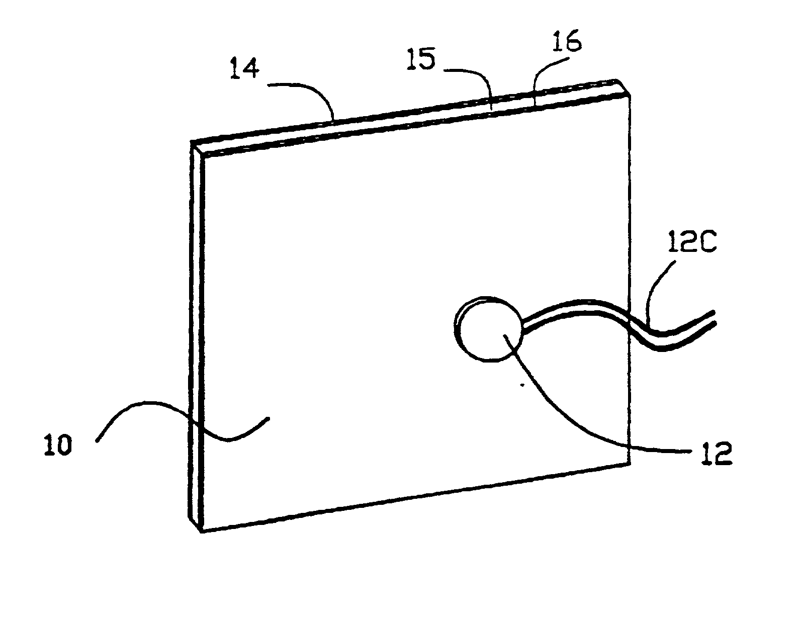
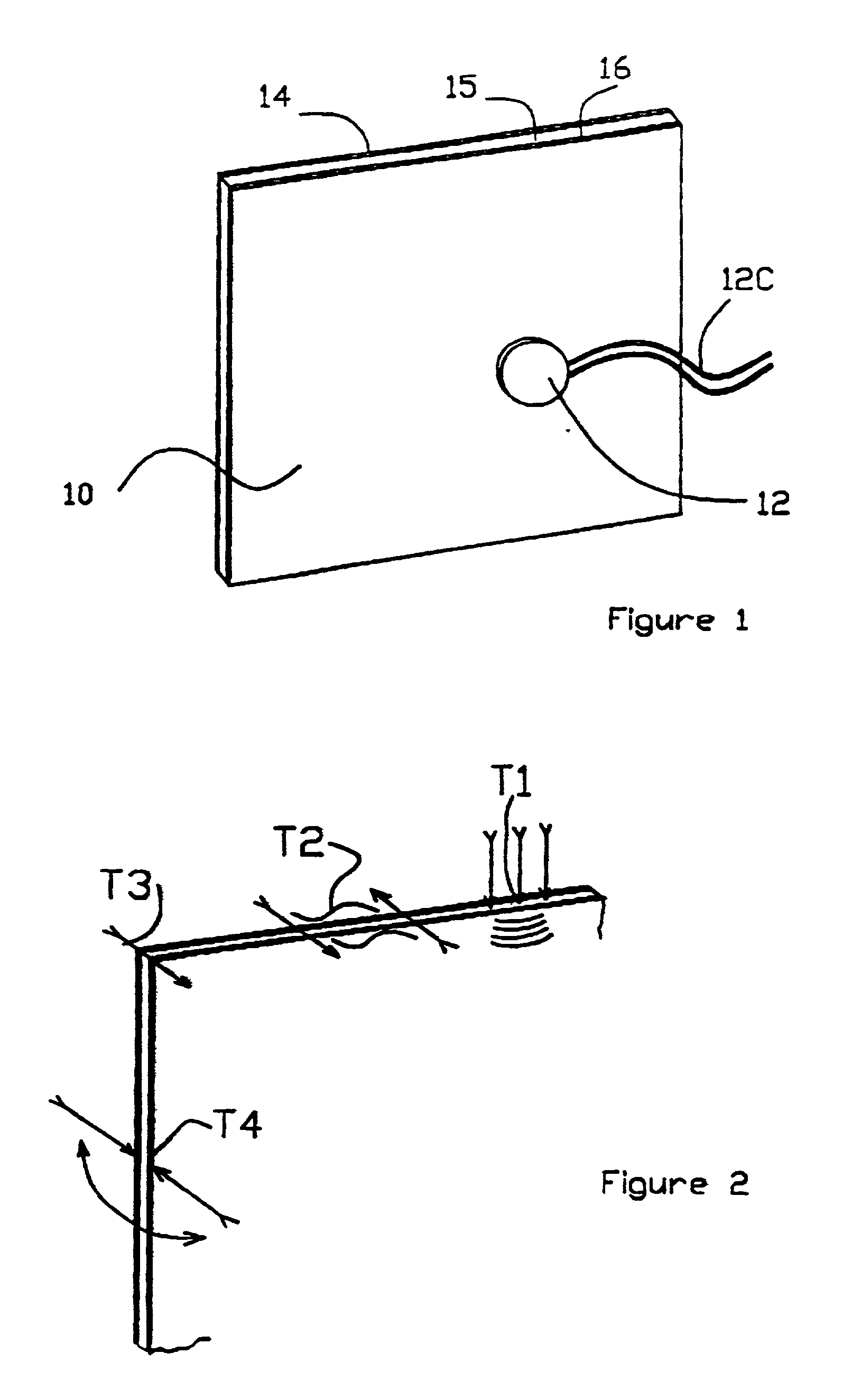
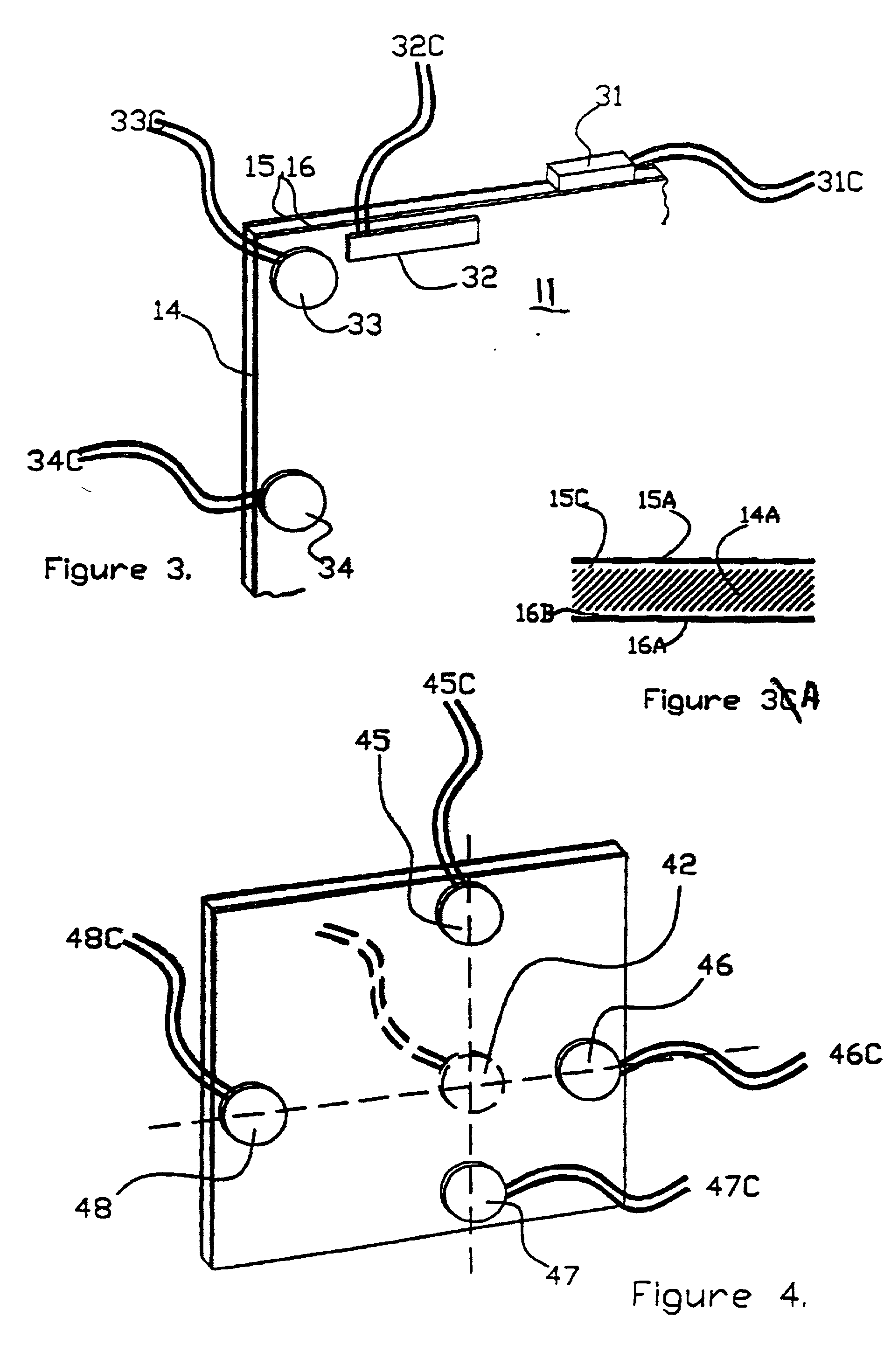
[0058] In FIG. 1, distributed mode acoustic panel loud-speaker 10 is as described in WO97 / 09842 with panel member 11 having typical optimal near-(but off-) centre location for drive means transducer 12. The sandwich structure shown with core 14 and skins 15, 16 is exemplary only, there being many monolithic and / or reinforced and other structural possibilities. In any event, normal in-board transducer placement potentially limits clear area available, e.g. for such as transmission of light in the case of a transparent or translucent panel.

[0059] Mainly transparent or translucent resonant mode acoustic panel members might use known transparent piezo-electric transducers, e.g. of lanthanum doped titanium zirconate. However these are relatively costly, hence the alternative approach thereof by which it is possible to leave the resonant mode acoustic panel member 10 mainly clear and unobstructed by optimising loudspeaker design from a choice of four types of excitation shown in FIG. 2 di...


PUM


Abstract

Active acoustic device comprises a panel member (11) having distribution of resonant modes of bending wave action determining acoustic performance in conjunction with transducer means (31-34). The transducer means (31-34) is coupled to the panel member (11) at a marginal position. The arrangement is such as to result in acoustically acceptable action dependent on said distribution of active said resonant modes. Methods of selecting the transducer location, or improvement by location of localised marginal clamping, rely on assessing best or better operative interaction of said transducer means (31-34) and the panel members (11) according to parameters of acoustic output for the device as an acoustic radiator.

Description

DESCRIPTION[0001] 1. Field of the Invention[0002] This invention relates to active acoustic devices and more particularly to panel members for which acoustic action or performance relies on beneficial distribution of resonant modes of bending wave action in such a panel member and related surface vibration; and to methods of making or improving such active acoustic devices.[0003] It is convenient herein to use the term "distributed model" for such acoustic devices, including acoustic radiators or loudspeakers; and for the term "panel-form" to be taken as inferring such distributed mode action in a panel member unless the context does not permit.[0004] In or as panel-form loudspeakers, such panel members operate as distributed mode acoustic radiators relying on bending wave action induced by input means applying mechanical action to the panel member; and resulting excitation of resonant modes of bending wave action causing surface vibration for acoustic output by coupling to ambient ...

Claims


Application Information

Patent Timeline
Patent Type & Authority Applications(United States)
IPC IPC(8): H04R1/24H04R5/02H04R7/04
CPCH04R1/24H04R5/02H04R7/045H04R2440/05H04R2499/15
Inventor AZIMA, FARADAZIMA, HENRYCOLLOMS, MARTINBANK, GRAHAMHILL, NICHOLAS
Owner NEW TRANSDUCERS LTD
Why Eureka
Try Eureka