

Base-station amplifier device
a technology of amplifier device and base station, which is applied in the direction of substation equipment, electrical equipment, power management, etc., can solve the problems of deterioration of radio characteristics, inability to perform linear amplification, and cdma mode being populated
- Summary
- Abstract
- Description
- Claims
- Application Information
AI Technical Summary
Problems solved by technology
Method used
Image

Examples
embodiment 1
[0020]
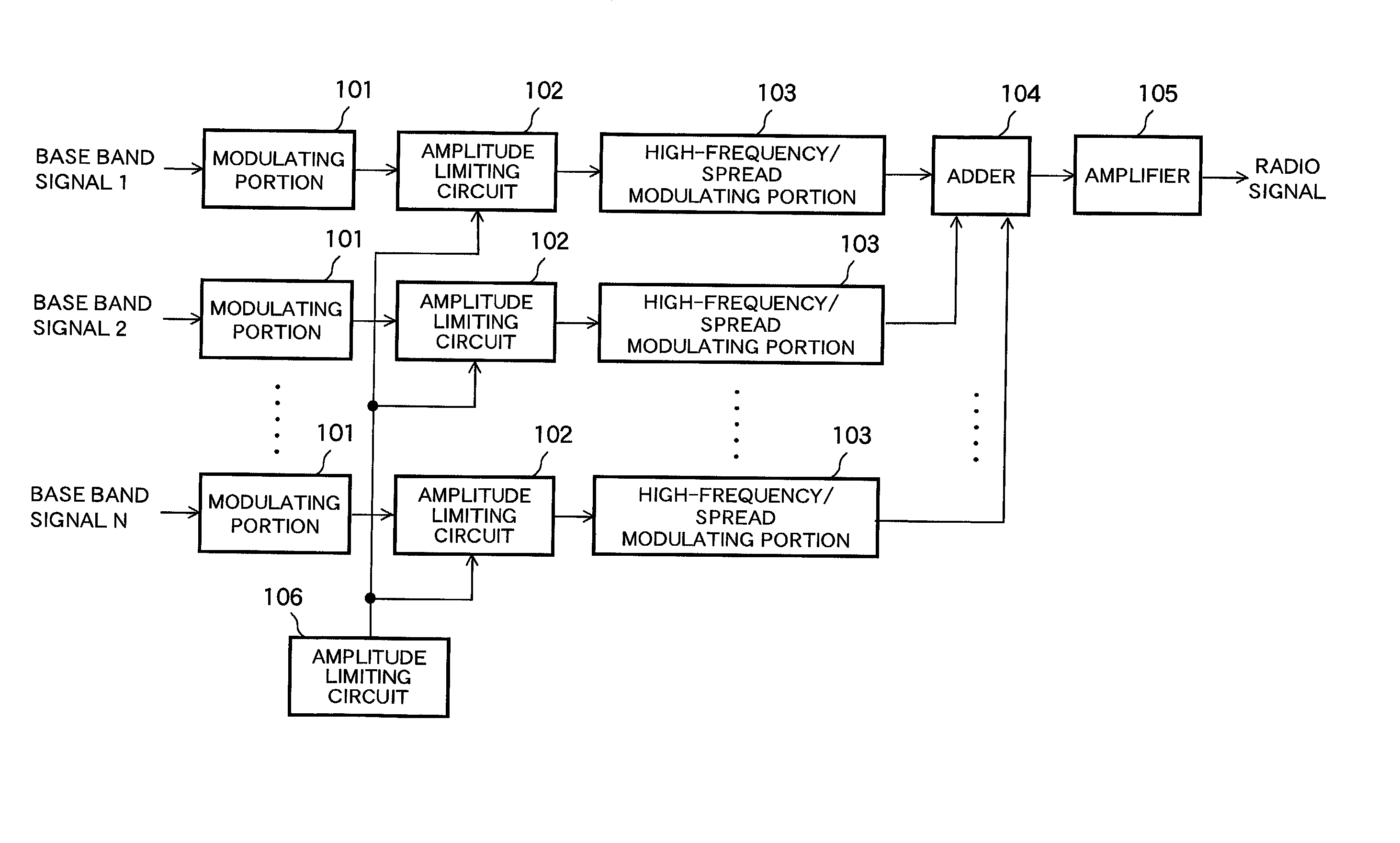
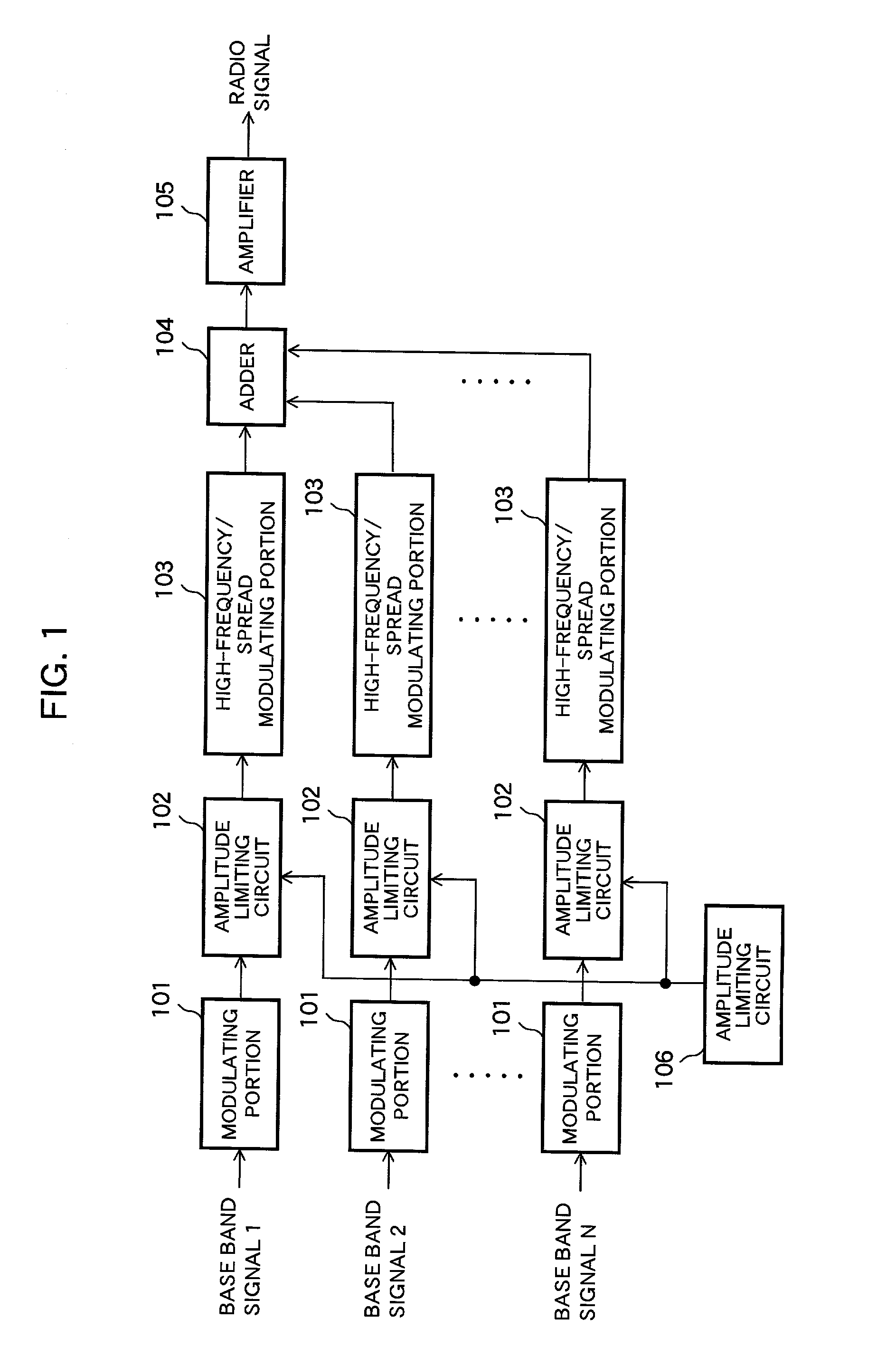
[0021] FIG. 1 is a block diagram showing an example of configuration of a base-station amplifier device according to a first embodiment of the present invention. As shown in FIG. 1, the base-station amplifier device comprises: a modulating portion 101; an amplitude limiting circuit 102; a high-frequency converting / spread modulating portion 103; an adder 104; an amplifier 105; and an amplitude controlling circuit 106. In this embodiment, there are N channels, i.e., channels 1-N, available for the base-station amplifier device as shown in FIG. 1, and base-band signals 1-N are allocated to the channels 1-N, respectively. Also, there are prepared N sets of the modulating portions 101, amplitude limiting circuits 102 and high-frequency converting / spread modulating portions 103 for the N channels in a one-to-one manner. Incidentally, the amplitude limiting circuit 102 is also referred to as "amplitude limiting means", the high-frequency converting / spread modulating portion 103 is al...
embodiment 2
[0028]
[0029] A base-station amplifier device according to a second embodiment of the present invention is configured similarly to that as shown in FIG. 1. In this second embodiment, the amplitude controlling circuit 106 conducts a determination for the amplitude control according to the number of channels. When the number of channels is small, i.e., at the time of a low traffic, transmitting power becomes small so that the amplitude controlling circuits 106 instructs the amplitude limiting circuits 102 not to perform an amplitude limitation on peak signal. On the contrary, when the number of channels is increased, i.e., at the time of a high traffic, the transmitting power is increased so that the amplitude controlling circuits 106 instructs the amplitude limiting circuits 102 to perform the amplitude limitation on peak signal because a backoff of the amplifier 105 is decreased.
embodiment 3
[0030]
[0031] FIG. 3 is a block diagram showing an example of configuration of a base-station amplifier device according to a third embodiment of the present invention. In FIGS. 1 and 3, the same or like numbers indicates the same or like parts and therefore explanations of such parts are omitted hereinafter. In particular, this third embodiment further comprises a detector circuit 201 arranged on a posterior stage of the amplifier 105. Incidentally, the detector circuit 201 is also referred to as "detecting means" in the present application.
[0032] The operation of this detector circuit 201 will be described with reference to FIGS. 4 and 5. FIG. 4 is a graph showing CCDF (Complementary Cumulative Distribution Function) characteristic and its different characteristics depending on whether the amplitude limitation being present or absent. In FIG. 4, an abscissa denotes peak power / average power while an ordinate denotes possibility exceeding the peak power / average power in the abscissa....
PUM
 Abstract
Description
Claims
Application Information