Crash optimized plunging CV joint

a technology of cv joints and cv shafts, which is applied in the direction of mechanical apparatus, rotary machine parts, couplings, etc., to achieve the effect of reducing mass and imbalance of vehicle propeller shafts, reducing mass and imbalance, and reducing the number of components used

Inactive Publication Date: 2003-01-09
GKN AUTOMOTIVE INC
View PDF0 Cites 52 Cited by
  • Summary
  • Abstract
  • Description
  • Claims
  • Application Information

AI Technical Summary

Benefits of technology

0008] The foregoing and other objects and advantages are provided by an apparatus for absorbing energy within a propeller shaft of a motor vehicle. A propeller shaft assembly including a constant velocity universal joint in a propeller shaft of a motor vehicle connecting a drive unit to a rear axle gearbox is provided. The universal joint includes at least two articulatably connected shaft portions, a hollow shaft, and a connecting shaft. The hollow shaft is connected to an outer joint part that has outer ball tracks. The hollow shaft has an aft open area and an exterior wall. The connecting shaft is connected to an inner joint part that has inner ball tracks. A plurality of torque transmitting balls are held by a cage and each are guided in one pair of corresponding outer and inner ball tracks. The ball cage holds the balls in a plane when the inner joint part is axially displaced or articulated. A standard plunge is included which is usable within a normal operating range in a damage-free way. The plunge has a fore plunge portion defined by a plane at a second stop, and an aft plunge portion defined by a plane at a first stop. The aft plunge portion and the aft open area having inner diameters that are greater then or equal to an inner diameter of the outer joint part. When the outer joint part is di

Problems solved by technology

The first stop is forcibly displaceable, however, such that the connecting shaft may release the firs

Method used


Image

  • Crash optimized plunging CV joint
  • Crash optimized plunging CV joint
  • Crash optimized plunging CV joint

Examples


Embodiment Construction

[0018] In the following description, various operating parameters and components are described for one constructed embodiment. These specific parameters and components are included as examples and are not meant to be limiting.

[0019] While the present invention is described with respect to an apparatus for absorbing energy within a propeller shaft of a vehicle the following apparatus is capable of being adapted for various purposes including: automotive vehicles, motor systems that use a propeller shaft, or other vehicle and non-vehicle applications that require energy absorption within a propeller shaft.

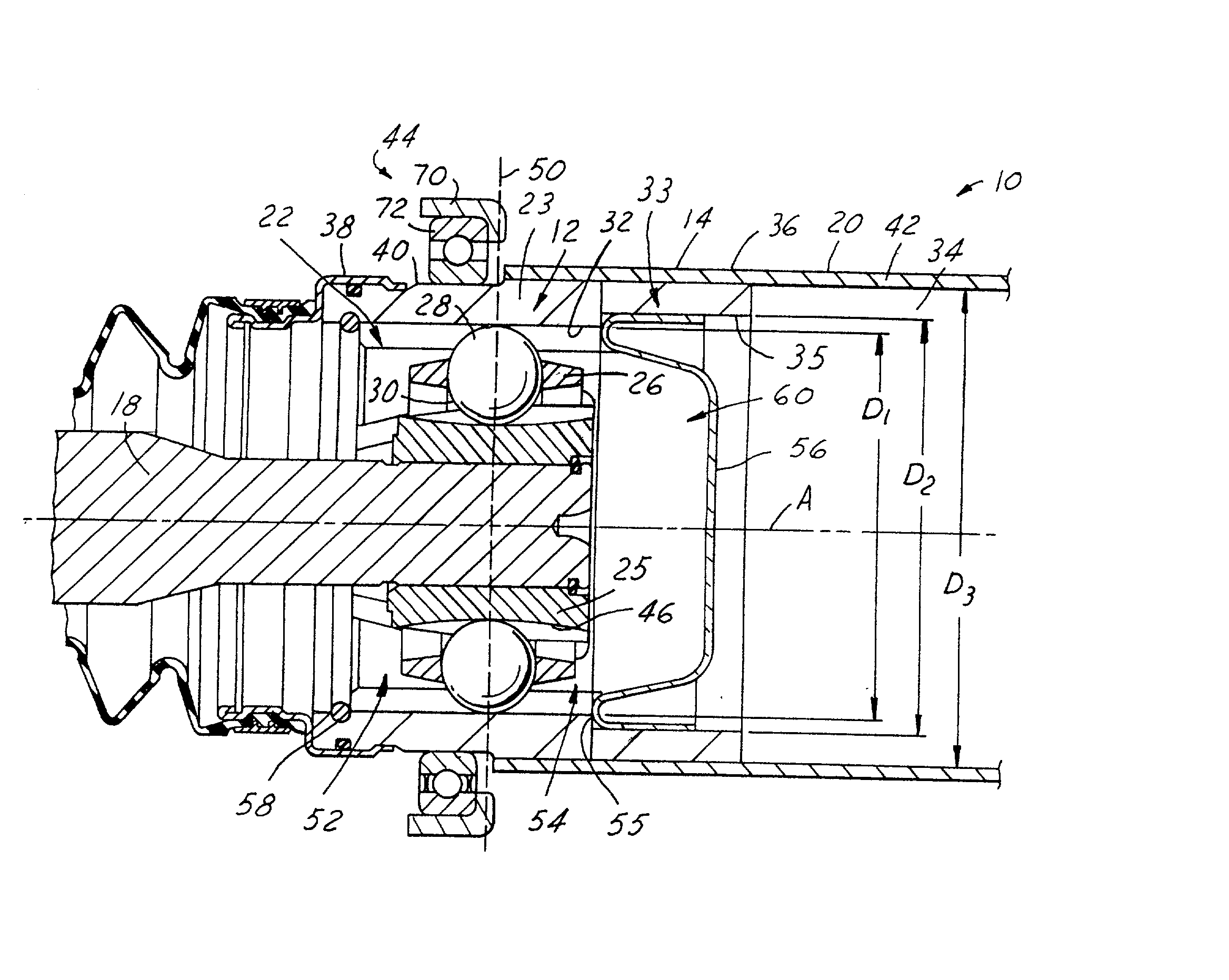
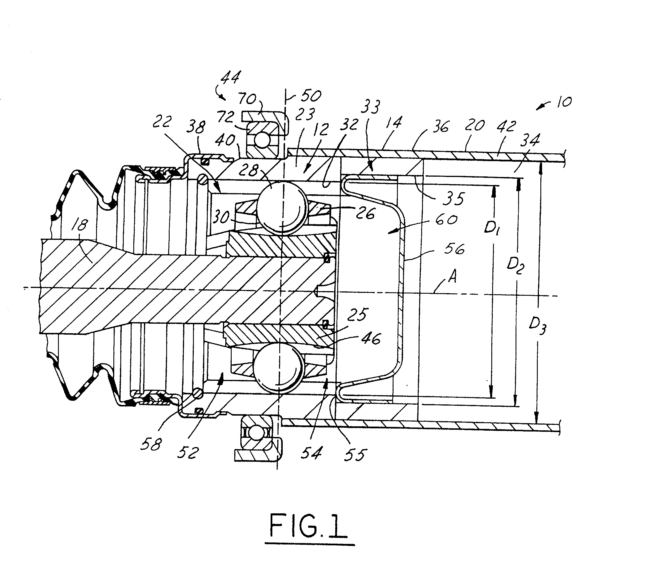
[0020] Referring now to FIG. 1, a cross-sectional view of a propeller shaft assembly 10 comprising a constant velocity (CV) universal joint 12 in a propeller shaft 14 of a motor vehicle positioned as if during "normal" operation and in accordance with the present invention is shown. Although the propeller shaft 14 of the present invention is illustrated as having two articulatable sh...


PUM


Abstract

A propeller shaft assembly (10) comprising a constant velocity universal joint (12) including a hollow shaft (20) and a connecting shaft (18) is provided. The hollow shaft (20) includes an aft open area (34) and is connected to an outer joint part (23) that has outer ball tracks (32). The connecting shaft (18) is connected to an inner joint part (25) that has inner ball tracks (46). A ball cage (26) that has a plurality of balls (28) is included. A standard plunge (22) that has an aft plunge portion (54) is also included. The aft plunge portion (54) and the aft open area (34) having inner diameters that are greater then or equal to an inner diameter D.sub.1 of the outer joint part (23). A first stop (55) limits the ball movement of travel in the aft direction. The first stop (55) is forcibly dispensable such that the connecting shaft (18) may release the first stop (55) and intrude significantly within the aft open area (34) which is outside a normal operating range (24).

Description

TECHNICAL FIELD[0001] The present invention relates generally to motor vehicle propeller shafts, and more particularly to an apparatus for absorbing energy within a propeller shaft of a motor vehicle.BACKGROUND OF THE INVENTION[0002] Two-piece propeller shafts are commonly used in motor vehicle propulsion. The two-piece propeller shaft is used when larger distances exist between a front drive unit and the rear axle of the vehicle. The two-piece propeller shaft transmits torque from the front drive unit to a rear axle. The two-piece propeller shafts are typically supported by a center-bearing and corresponding support bracket. The center-bearing and support bracket support the center of the propeller shaft while still allowing the drive shaft to rotate and transfer mechanical energy from the front drive unit to the rear axle.[0003] Besides transferring mechanical energy, it is desirable for propeller shafts to have adequate crashworthiness, be lightweight, easy and inexpensive to man...

Claims


Application Information

Patent Timeline
IPC IPC(8): F16D3/226
CPCF16D3/226F16D2003/2232F16D2300/12Y10S464/906
Inventor BOUTIN, ROBERT ANTHONY
Owner GKN AUTOMOTIVE INC
Why Eureka
Try Eureka