
Lift for vehicles

Inactive Publication Date: 2003-01-23
GIULIANO GROUP
View PDF0 Cites 5 Cited by
  • Summary
  • Abstract
  • Description
  • Claims
  • Application Information

AI Technical Summary

Benefits of technology

[0009] The aim of the present invention is to eliminate the above-noted drawbacks of the prior art by providing a lift for vehicles whose structure is sturdy and stable when loaded.
[0010] Within the scope of this aim, an object of the present invention is to provide a lift for vehicles which allows full access to the vehicle, maintaining a small space occupation and a structure which does not hinder to an unsurmountable extent the possibility to move the vehicles inside the garages.
[0011] Another object of the present invention is to provide operators with a lift for vehicles which has adequate supports for the stable and safe resting of precision instruments normally used for measurements and corrections of the trim of vehicles.

Problems solved by technology

The first type of lift is substantially sturdier and more stable when loaded but is less practical in use and has a greater overall space occupation.
The posts, which are fixed, limit operator access to the vehicle in the regions where the posts are present, and even when the lift is not loaded and is not in use they obstruct the passage of vehicles during movement within the garages in which the lifts are placed.
The second type of lift is less awkward to use and is far more compact than the preceding one, but this is achieved at the cost of generally lower stability when loaded.

Method used


Image

  • Lift for vehicles
  • Lift for vehicles
  • Lift for vehicles

Examples


Embodiment Construction

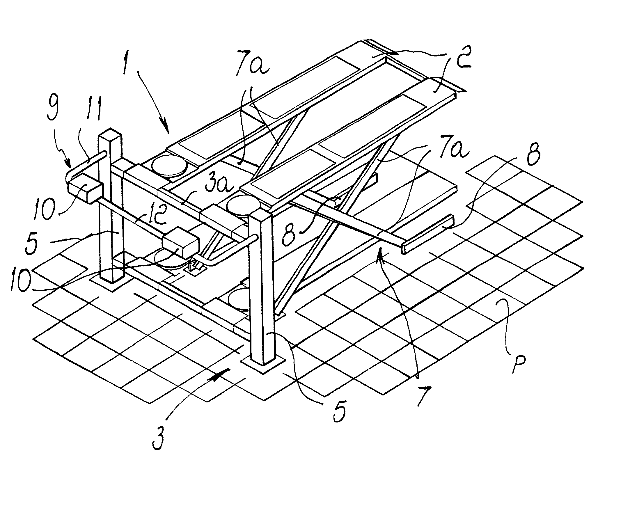
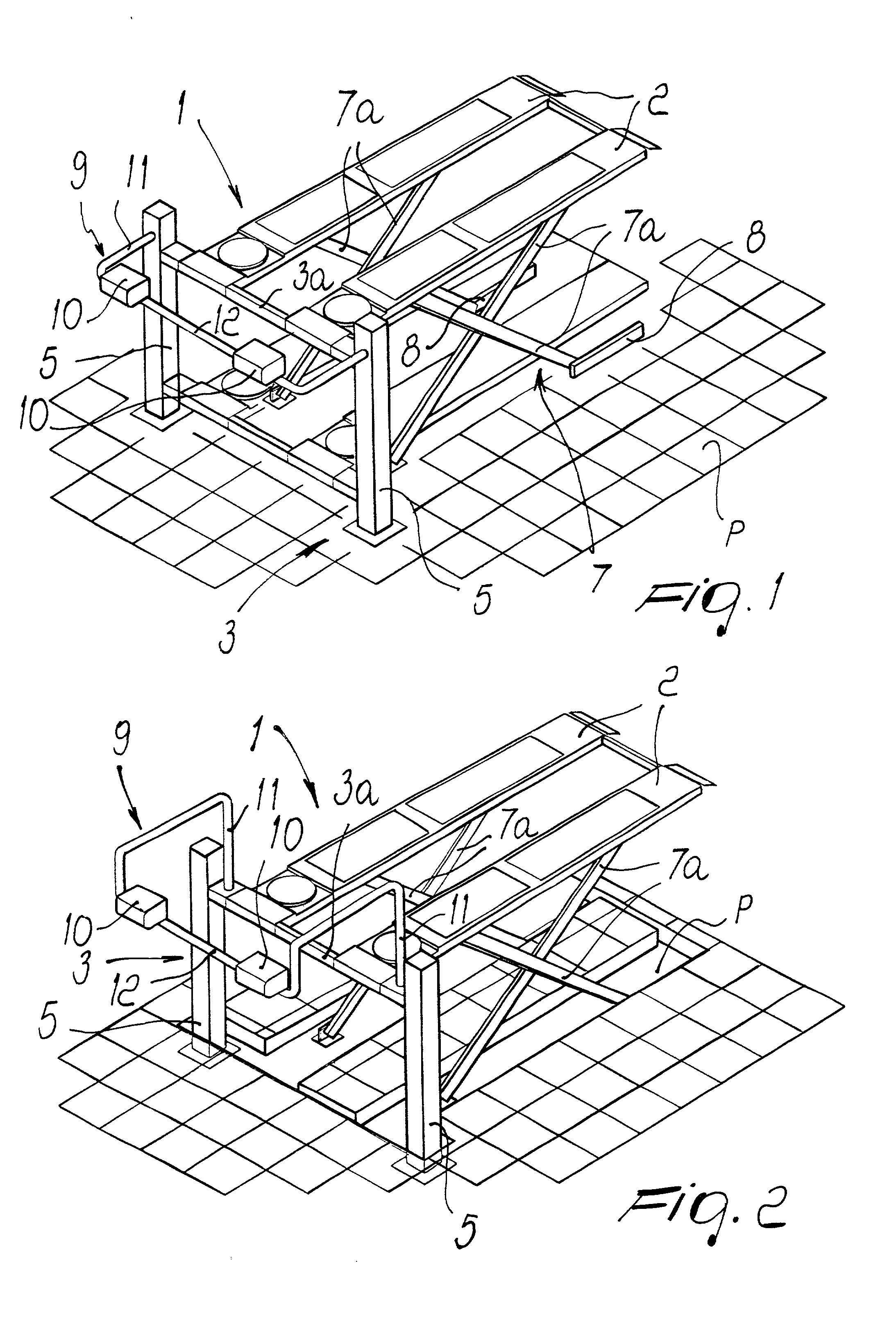
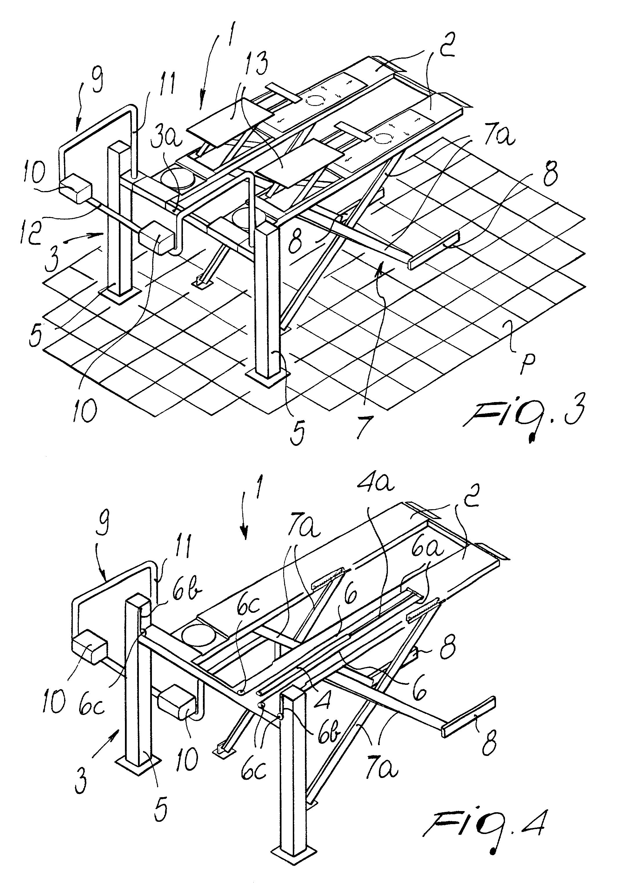
[0018] With reference to the figures, 1 designates a lift for vehicles comprising two parallel ramps 2 onto which the vehicles are loaded and which can be actuated so as to move vertically.

[0019] The two ramps 2 have, for this purpose, two corresponding ends which are rigidly coupled to the cross-member 3a of a portal-like frame 3; the cross-member 3a can be actuated with a vertical translational motion parallel to itself by way of corresponding conventional means, constituted for example, as shown in FIG. 4, by a hydraulic or pneumatic actuator 4 which acts by pulling two cable-like traction elements 6 whose respective ends 6a and 6b are rigidly coupled to the end of the stem 4a of said actuator and, after passing around a series of guide pulleys 6c, to a pair of posts 5 which compose the frame 3 and along which, as mentioned, the cross-member 3a is movable.

[0020] In the lower parts of each ramp 2 corresponding grid-like frames 7 are provided which are composed of rods 7a being piv...


PUM


Abstract

A lift for vehicles comprises two parallel ramps for loading the vehicles which can be actuated so as to move vertically. The ramps have concurrent ends which are rigidly coupled to the cross-member of a portal-like frame, with the cross-member being actuatable with a vertical translational parallel motion by way of corresponding actuation along a pair of posts. Corresponding grid-like frames, with rods hinged in a scissor-like arrangement for the constant resting of said ramps on a resting surface and / or floor, are provided below each ramp.

Description

BACKGROUND OF THE INVENTION[0001] The present invention relates to a lift for vehicles.[0002] Lifts for vehicle substantially comprising two parallel ramps on which the vehicles are positioned for being lifted, inspected and to perform maintenance have long been used in garages.[0003] According to their structure, the auto lifts or hoists are divided into two main categories: in a first oldest one, the ramps are associated and moved vertically by sliding on four posts; in a second more recent one, each ramp has its own lifting frame of the so-called scissor-like type, and such frames are circuitally or mechanically interconnected so as to move in step, maintaining the parallel arrangement of the ramps.[0004] The first type of lift is substantially sturdier and more stable when loaded but is less practical in use and has a greater overall space occupation.[0005] The posts, which are fixed, limit operator access to the vehicle in the regions where the posts are present, and even when ...

Claims


Application Information

Patent Timeline
IPC IPC(8): B66F7/08
CPCB66F7/08B66F7/065
Inventor VIGNOLI, GIULIANO
Owner GIULIANO GROUP
Learn More