

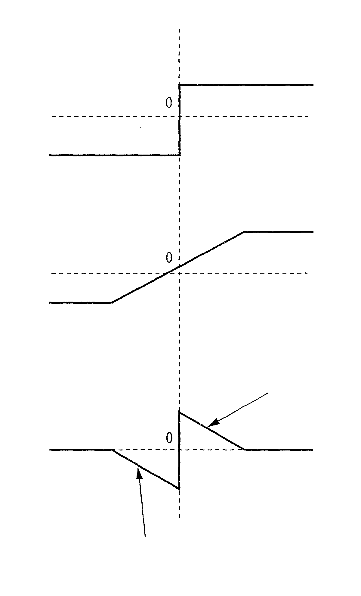
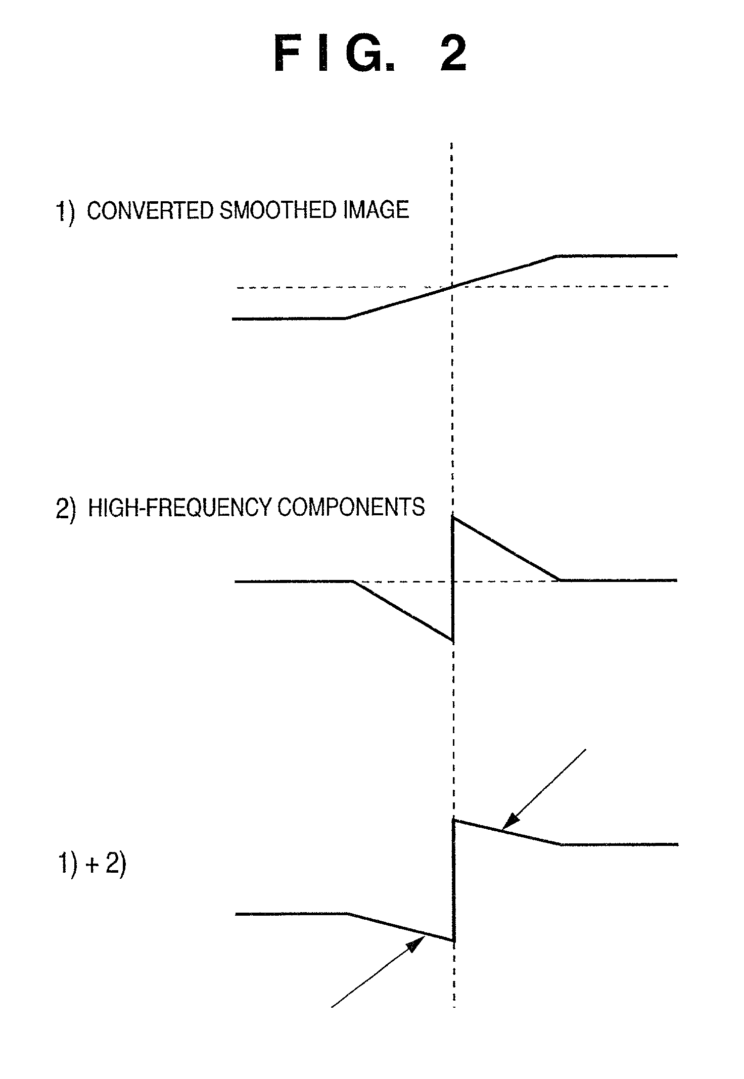
Image processing apparatus, image processing method, storage medium, and program
a technology of image processing apparatus and image processing method, which is applied in the field of image processing apparatus, image processing method, storage medium, and program, can solve the problems of difficult to obtain an x-ray chest image that allows, unable to perfectly preserve the edge structure, and parts where high-frequency components are suppressed become unnatural, so as to achieve the effect of suppressing or avoiding the collapse of the edge structure of an imag
- Summary
- Abstract
- Description
- Claims
- Application Information
AI Technical Summary
Benefits of technology
Problems solved by technology
Method used
Image

Examples
embodiment 1
[0112] FIG. 8 shows an X-ray photographing apparatus 100 according to The X-ray photographing apparatus 100 has a function of executing processes for respective frequency bands of a taken image, and comprises a pre-processing circuit 106, CPU 108, main memory 109, control panel 110, image display 111, and image processing circuit 112, which exchange data via a CPU bus 107.
[0113] The X-ray photographing apparatus 100 also comprises a data acquisition circuit 105 connected to the pre-processing circuit 106, and a two-dimensional X-ray sensor 104 and X-ray generation circuit 101, which are connected to the data acquisition circuit 105, and these circuits are also connected to the CPU bus 107.
[0114] In the aforementioned X-ray photographing apparatus 100, the main memory 109 stores various data and the like required for the processing by the CPU 108, and serves as a work memory for the CPU 108.
[0115] The CPU 108 executes operation control and the like of the overall apparatus in accord...
embodiment 2
[0138] Embodiment 2 will be described below along with the flow of processes shown in FIG. 14. A description of the same processes as those in Embodiment 1 will be omitted.
[0139] The DWT circuit 114 executes a DWT process of an original image Org(x, y). Let horgn(x, y) be each image component obtained by that process (s701). The tone conversion circuit 113 executes a tone conversion process of the original image Org(x, y) using a tone conversion curve f( ) (s702). The DWT circuit 114 executes a DWT process of the image f(Org(x, y)) that has undergone the tone conversion process to obtain image components hn(x, y) (s703). Note that n indicates the subband category and x and y are the coordinates as in Embodiment 1.
[0140] The component conversion circuit 115 converts the image component horgn(x, y) by: 2 h2n ( x , y ) = hn ( x , y ) + ( 1 - f '( Org ( x , y ) )) .times. horgn ( x , y ) ( 17 )
[0141] and adds the converted component to the image component hn(x, y), thus obtaining a newl...
embodiment 3
[0150] Embodiment 3 will be described along with the flow of processes shown in FIG. 15. A description of the same processes as those in Embodiment 1 will be omitted.
[0151] The tone conversion circuit 113 executes a tone conversion process of an original image Org(x, y) using a tone conversion curve f( ) to obtain a processed image f(Org(x, y) (s801). The DWT circuit 114 then executes a DWT process of the original image to obtain image components hn(x, y) (s802). Note that n indicates the subband category and x and y are the coordinates as in Embodiment 1.
[0152] The component conversion circuit 115 converts each image component hn(x, y) by:
h2n(x, y)=(1-f'(Org(x, y))).times.hn(x, y) (20)
[0153] to obtain a new image component h2n(x, y) (s803).
[0154] Note that the values of the lowest frequency component LL are set to be all 0s (zeros).
[0155] In this way, by computing the inverse DWTs of h2n(x, y), an image Hr(x, y) consisting of only high-frequency components depending on the slope of...
PUM
 Abstract
Description
Claims
Application Information