Apparatus for in-line surface polishing of cylindrical stock such as stainless steel tubing, and method

a technology of cylindrical stock and in-line surface polishing, which is applied in the direction of grinding drives, grinding machine components, manufacturing tools, etc., can solve the problems of inability to machine-process parts such as handles, variability of quality and appearance, and the cost of manually carrying out the process. to achieve the effect of increasing the length of the scratch finish

Inactive Publication Date: 2003-01-30
MCCOY REBECCA HARRIS
View PDF0 Cites 34 Cited by
  • Summary
  • Abstract
  • Description
  • Claims
  • Application Information

AI Technical Summary

Benefits of technology

[0017] It is another object of the invention to provide a method for in-line surface finishing of cylindrical stock such as stainless steel tubing which achieves a brushed finish wherein the scratch pattern extends longitudinally along the length of the tubing and thus avoids the appearance of rings around the tubing characteristic of prior art machine polishing processes.
[0020] According to another preferred embodiment of the invention, a stock-engaging backup support is positioned for engagement with the rotating stock against the direction of rotation of the stock for preventing lateral displacement of the stock by the stock rotating wheel.
[0032] According to yet another preferred embodiment of the invention, the method includes the step of engaging the rotating stock against the direction of rotation of the stock for preventing lateral displacement of the stock as it rotates.
[0038] According to yet another preferred embodiment of the invention, the method includes the step of supporting the belt on a pair of idler rollers positioned upstream and downstream, respectively, of the rotating finish wheel, the idler rollers being positioned to elongate the area of contact between the belt and the stock to increase the length of the scratch finish applied to the stock.
[0051] The polishing wheel 15 is 2 inches wide and is formed of four 16 inch sisal polishing wheels cut down to a 12 inch diameter and held in place to expose a radially-extending perimeter of approximately 1 / 4 inch of sisal. The outer two sisal wheels are preferably hard 8-ply model TR-6151 manufactured by Schaffner Manufacturing Company, Pittsburgh, Pa. The inner two sisal wheels are preferably soft 12-ply 15-section sisal wheels manufactured by Schaffner Manufacturing Company, Pittsburgh, Pa. It should be noted that the polishing wheel 15 itself does not contact the tubing "T" at any time. The sisal surface of the polishing wheel 15 provides a controlled amount of "give" which permits the belt 32 to assume a slightly concave shape mated to the surface of the tubing "T" passing beneath as well as increasing friction between the polishing wheel 15 and belt 32 to prevent lateral movement of the belt 32.

Problems solved by technology

However, certain parts such as handles cannot presently be machine-processed to impart a brushed finish which will match the brushed finish on the doors, sides top and other visible surfaces.
This prior art practice presents several disadvantages, including the expense of carrying out this process manually instead of automatically and the variability of quality and appearance resulting from variation in the skill of the person carrying out the process.
However, the radial pattern applied by prior art machine polishing processes is clearly undesirable, since it does not match the long scratch pattern of brushed stainless steel used on commercial and high end residential appliances.

Method used


Image

  • Apparatus for in-line surface polishing of cylindrical stock such as stainless steel tubing, and method
  • Apparatus for in-line surface polishing of cylindrical stock such as stainless steel tubing, and method
  • Apparatus for in-line surface polishing of cylindrical stock such as stainless steel tubing, and method

Examples


Embodiment Construction

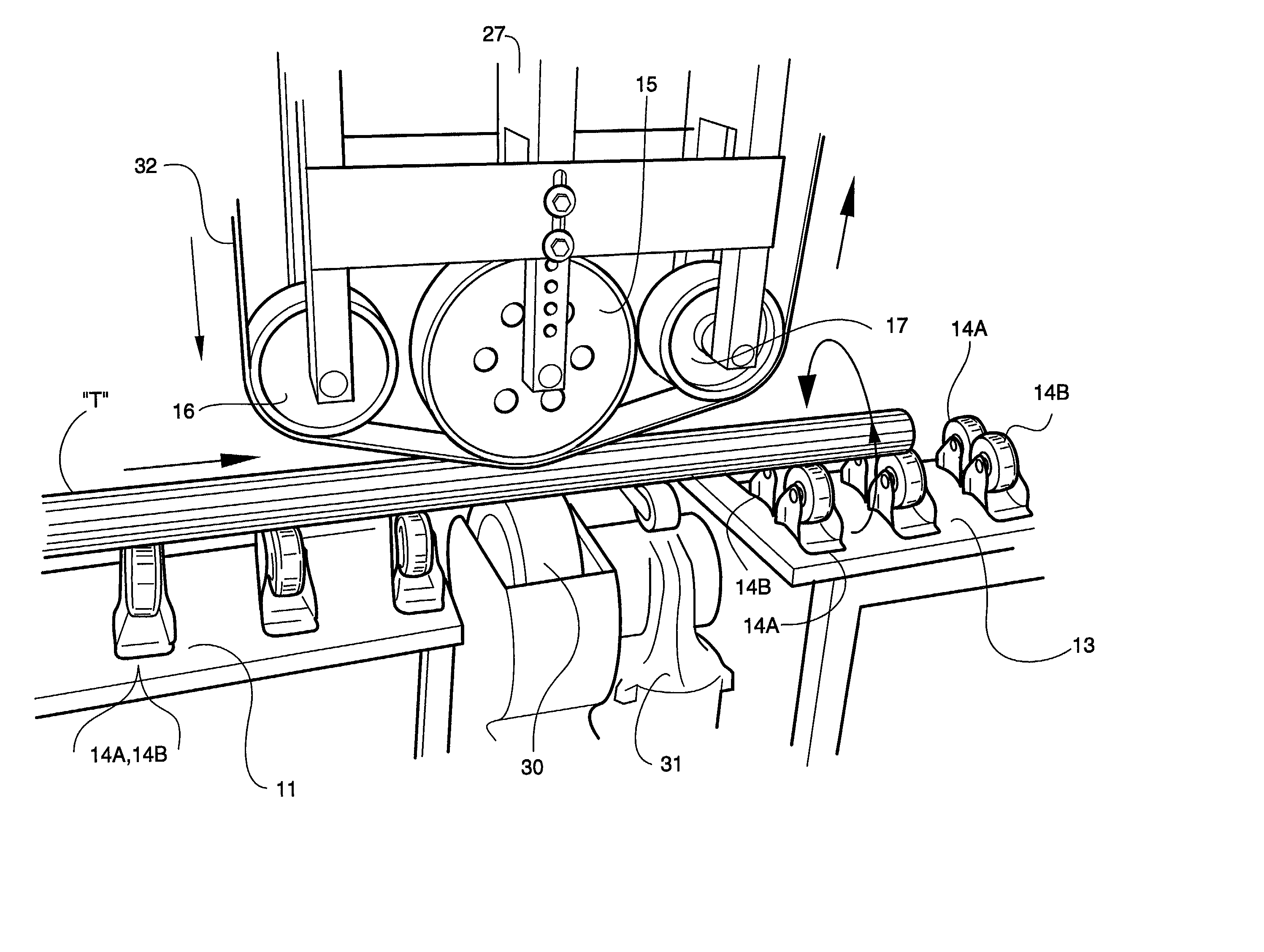
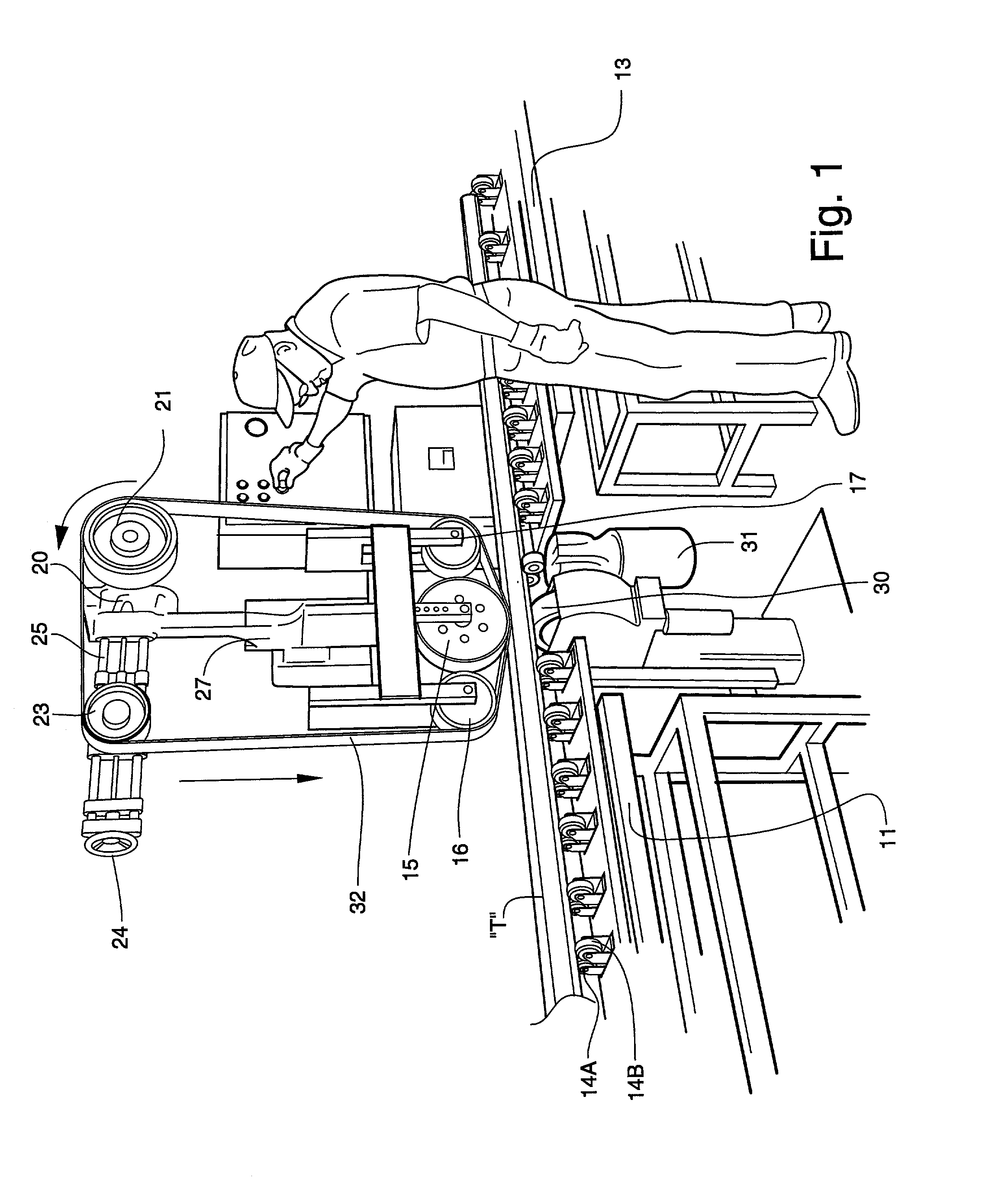
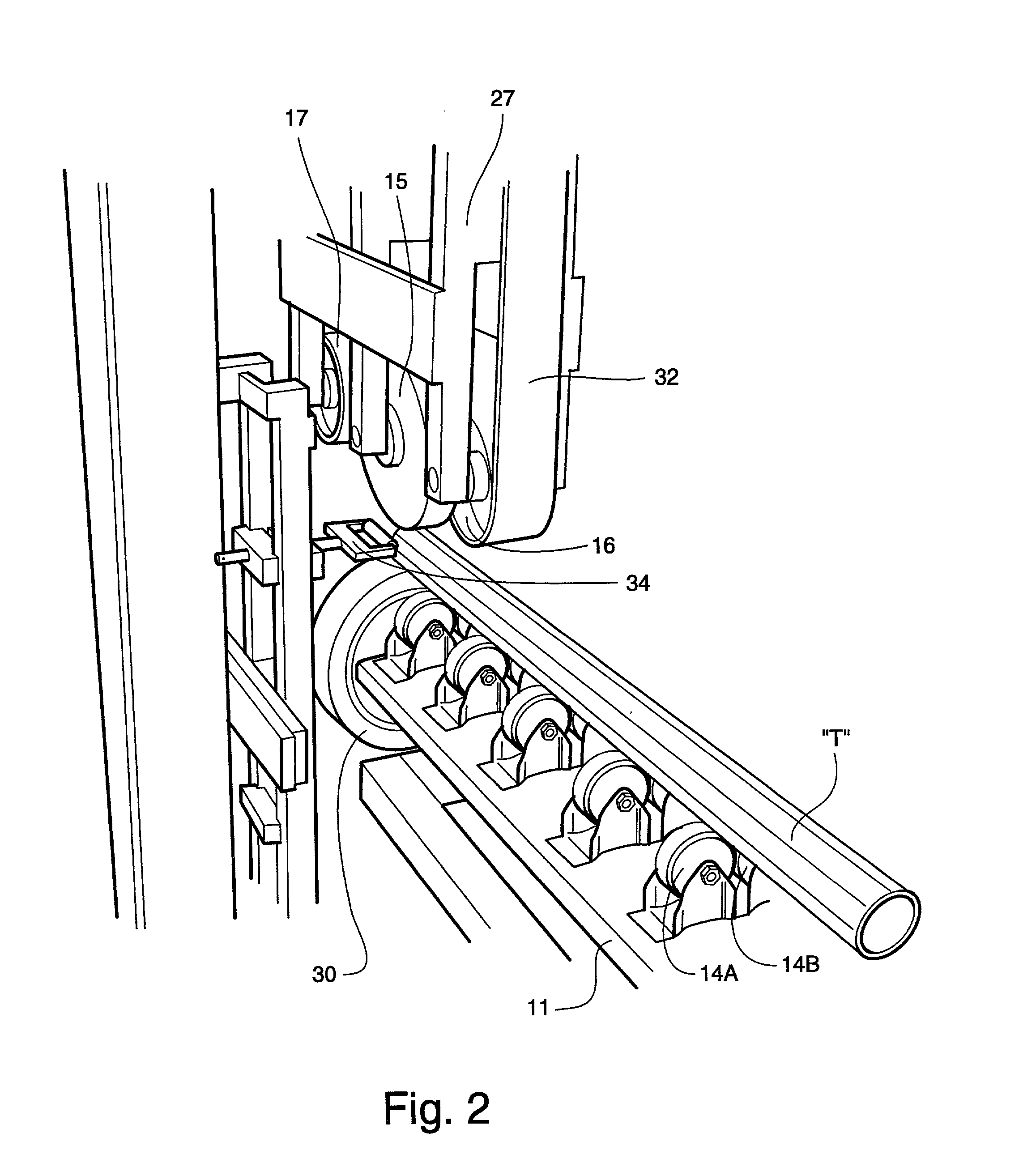
[0046] Referring now to FIG. 1, a polishing apparatus 10 according to one embodiment is shown. Tubing "T" is fed along an infeed table 11 to a polishing assembly 12 where the tubing is polished as described below. The tubing then passes downstream along an outfeed table 13 and to downstream processes. The tubing "T" is supported by numerous paired support rolls 14A, 14B which extend along the length of the infeed table 11 and outfeed table 13 at an offset of 4 degrees relative to the perpendicular to the infeed axis of the tubing "T". The infeed table 11 and outfeed table 13 are vertically adjustable to accommodate tubing of differing diameters and for fine adjustment.

[0047] The polishing assembly includes a polishing wheel 15 and two adjacent idler wheels 16 and 17. Tension is adjusted by a tension adjustment apparatus which includes a tension pulley 23 controlled by a tension adjustment wheel 24. The tension pulley 23 is mounted on tension adjustment bars 25 by which the distance ...


PUM

PropertyMeasurementUnit
lengthaaaaaaaaaa
angleaaaaaaaaaa
diameteraaaaaaaaaa

Abstract

A surface finishing apparatus for in-line outer surface polishing of elongate cylindrical metal stock to apply a long scratch finish, including a stock feeder for feeding a length of stock through the finishing apparatus from an infeed downstream to an outfeed position while rotating the stock about its longitudinal axis and a polishing assembly for finish-treating the outer surface of the stock as the stock is fed through the apparatus to apply a long scratch finish thereto. The polishing assembly includes a rotatable finishing wheel having a finish-treating peripheral surface for being applied in an in-line orientation against the outer surface of the stock as the stock is simultaneously fed and rotated through the finishing apparatus. The finishing wheel is mounted on an axis of rotation which is perpendicular to the longitudinal axis of the stock, and is rotated at a speed sufficiently great in comparison to the speed of rotation of the stock that the scratch finish applied to the stock is linear and extends substantially along the longitudinal axis of the stock.

Description

TECHNICAL FIELD AND BACKGROUND OF THE INVENTION[0001] This application is based on and claims priority from Provisional Patent Application Serial No. 60 / 308,083, filed on Jul. 26, 2001.[0002] This invention relates to an apparatus for in-line surface finishing elongate cylindrical stock, for example, stainless steel tubing, and a method for in-line surface finishing of cylindrical stock such as stainless steel tubing. Use of the term "in-line" is used in this application to mean that the scratch pattern of the surface finish applied to the stock extends substantially parallel to, or linearly along, the longitudinal axis of the stock. Applicant's prior patent, U.S. Pat. No. 5,759,089, for example, discloses an apparatus and method for buffing the surface of stainless steel tubing to achieve a chrome-bright finish. The scratch pattern extends generally along the length of the tubing. However, the buffing process described in the above-referenced patent randomizes the scratch pattern b...

Claims


Application Information

Patent Timeline
Patent Type & Authority Applications(United States)
IPC IPC(8): B24B5/38B24B21/02B24B47/22
CPCB24B5/38B24B21/025B24B47/22
Inventor MCCOY, THOMAS
Owner MCCOY REBECCA HARRIS
Why Eureka
Try Eureka