
Gravimetric blender with manually removable hoppers having integral interior valves

a technology of interior valves and hoppers, applied in the field ofgravimetric blenders, can solve problems such as defective products

Inactive Publication Date: 2003-02-06
MAGUIRE STEPHEN B
View PDF91 Cites 17 Cited by
  • Summary
  • Abstract
  • Description
  • Claims
  • Application Information

AI Technical Summary

Problems solved by technology

One of these may be "regrind", consisting of ground plastic resin which had previously been molded or extruded and which either resulted in a defective product or was excess material not formed into a desired product.

Method used


Image

  • Gravimetric blender with manually removable hoppers having integral interior valves
  • Gravimetric blender with manually removable hoppers having integral interior valves
  • Gravimetric blender with manually removable hoppers having integral interior valves

Examples


Embodiment Construction

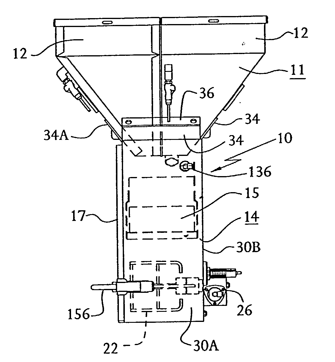
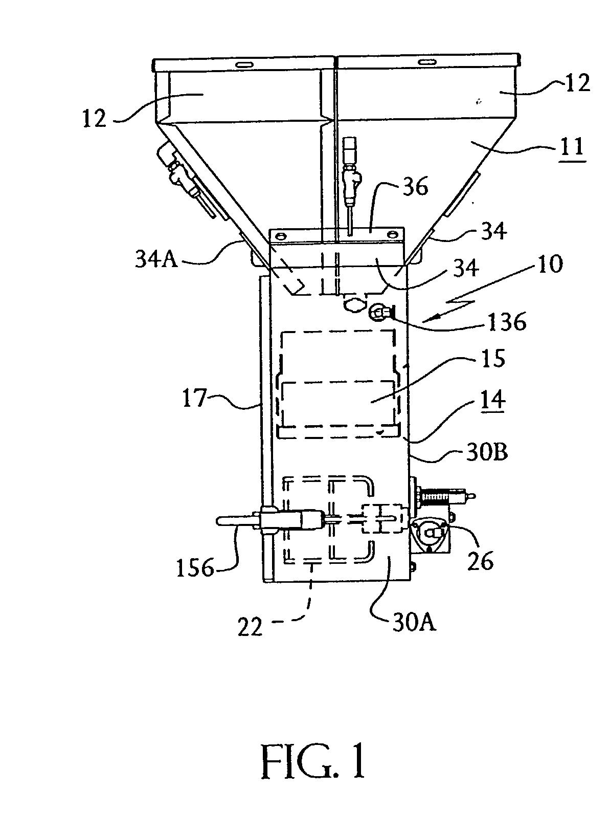
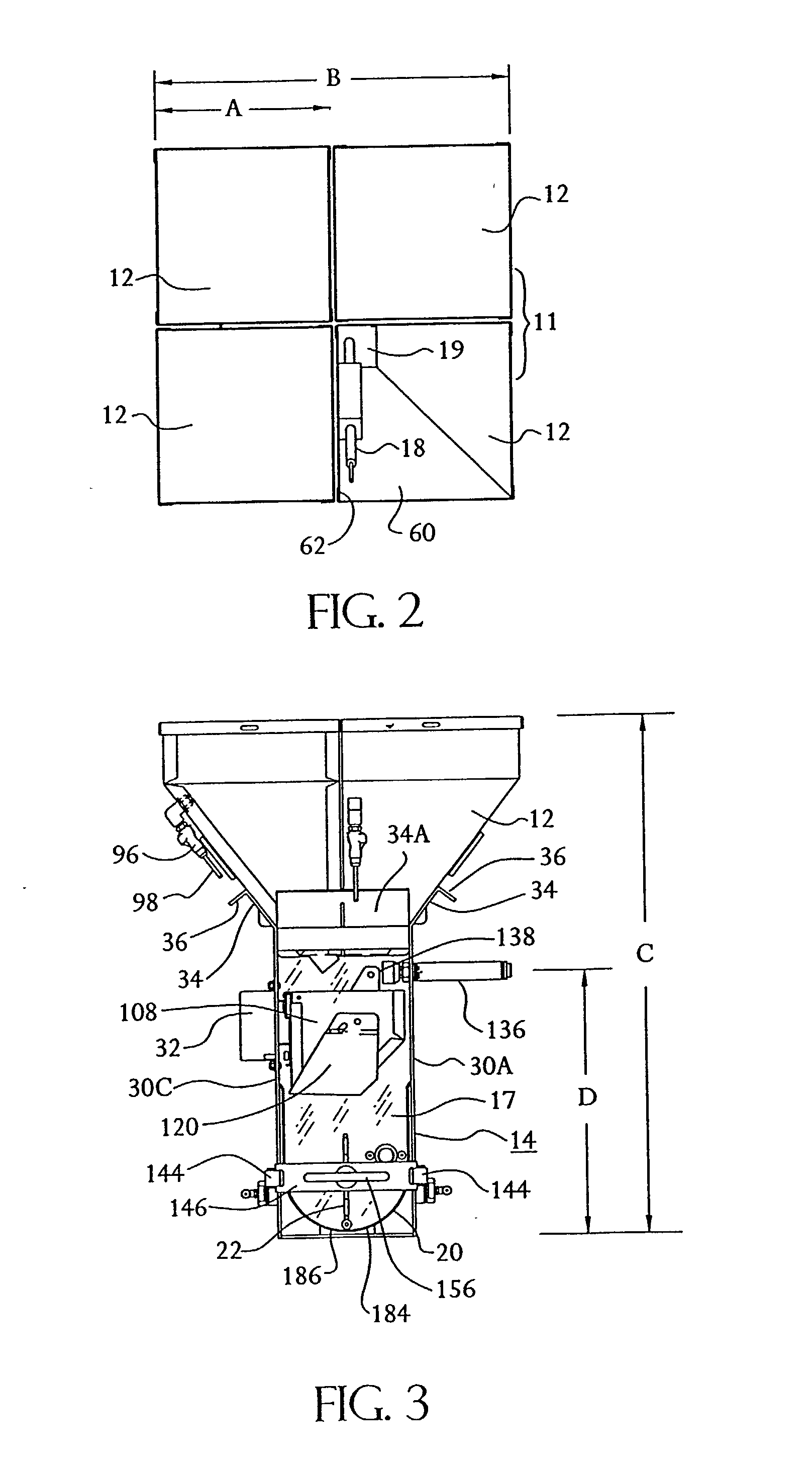
[0033] Referring to the drawings and to FIGS. 1-3 in particular, a gravimetric blender is designated generally 10 and includes a hopper assembly 11 including a plurality of hoppers, which are individually designated generally 12. The collection of hoppers 12, each of which is individually removable from blender 10 manually, without the use of tools, is supported by a frame designated generally 14 which holds a weigh bin 15 into which portions of solid plastic resin or other granular or powdery material can be metered and weighed prior to release into a mix chamber as described below.

[0034] Frame 14 preferably includes four upstanding side panel members, three of which are preferably steel and formed from a single sheet, bent to form the three sides, with the three sides being identified 30A, 30B and 30C. The remaining front side panel of frame 14, which is removable and detachable from sides 30, is designated 17 in the drawings and is preferably clear, transparent plastic.

[0035] Hop...


PUM

PropertyMeasurementUnit
angleaaaaaaaaaa
longitudinal displacementaaaaaaaaaa
weightaaaaaaaaaa

Abstract

A valve for downwardly dispensing a precisely controlled flow of granular material from a material storage device has a discharge orifice proximate a lower extremity thereof and includes an axially reciprocable tubular member aligned with and slidable axially upwardly and downwardly within the orifice, having a lateral material intake port formed therein remote from vertical extremities of the member, a lower end member being open to define a discharge orifice for granular material dispensed therby, a chamber at least partially surrounding the tubular member, having an open lower end confronting and spaced above the orifice, the chamber open end affording flow of material from the storage device through the port and into the tubular member when the tubular member is at a first position below the open end, the port being spaced upwardly from the open end when the tubular member is at a second position and a pneumatic piston for moving the tubular member axially between the first and second positions.

Description

CROSS REFERENCE TO RELATED PATENT APPLICATIONS[0001] This application is a division of U.S. patent application Ser. No. 08 / 989,352, filed Dec. 12, 1997, which in turn was based on provisional U.S. patent applications Ser. No. 60 / 032,831, filed Dec. 13, 1996 and 60 / 045,343, filed May 4, 1997, the benefit of the priority of both of which was claimed under 35 USC 119, and further was a continuation-in-part of U.S. design patent application Ser. No. 29 / 071,503 filed May 30, 1997 (which issued May 9, 2000 as U.S. Pat. No. D424,587) the priority of which was claimed under 35 USC 120; this application makes these same priority claims under 35 USC 119 and 120.[0002] This invention relates generally to methods and apparatus for providing precisely measured amounts of granular materials preparatory to further processing of the combined granular materials and specifically to gravimetric blenders providing precisely measured amounts of plastic resin material and mixing these components prior to...

Claims


Application Information

Patent Timeline
Patent Type & Authority Applications(United States)
IPC IPC(8): G01G19/30B01FB01F3/18B01F15/00B01F15/02B01F15/04B67D3/00G01G13/18
CPCB01F3/18B01F15/00805B01F15/02B01F15/0201B01F15/0445G01G13/02G01G13/18B29B7/244B29B7/603B29B7/283B29B7/728B29B7/78B01F23/60B01F35/453B01F35/881B01F35/71805B01F35/71731
Inventor MAGUIRE, STEPHEN B.
Owner MAGUIRE STEPHEN B
Learn More