Device for the attachment of an engine to an aircraft

a technology for aircraft and engines, applied in the direction of machines/engines, efficient propulsion technologies, machine supports, etc., can solve the problems of inability to preserve this integrity, inability to use the attachment device, and the loading of the four bolts is not uniform

Inactive Publication Date: 2003-02-06
AIRBUS OPERATIONS (SAS)
View PDF0 Cites 49 Cited by
  • Summary
  • Abstract
  • Description
  • Claims
  • Application Information

AI Technical Summary

Problems solved by technology

However, they are not able to preserve this integrity if the failure concerns the link between the pylon and the bracket, i.e. for example the attachment bolts connecting these two items or the intermediate part, if the latter exists.
Moreover, the combination of main and standby attachment functions through separate additional items leads to attachment devices which are both heavier and more complex.
Additionally, when the loads to be transmitted are very large, in particular in the case of heavy high-thrust engines, it ma

Method used


Image

  • Device for the attachment of an engine to an aircraft
  • Device for the attachment of an engine to an aircraft
  • Device for the attachment of an engine to an aircraft

Examples


Embodiment Construction

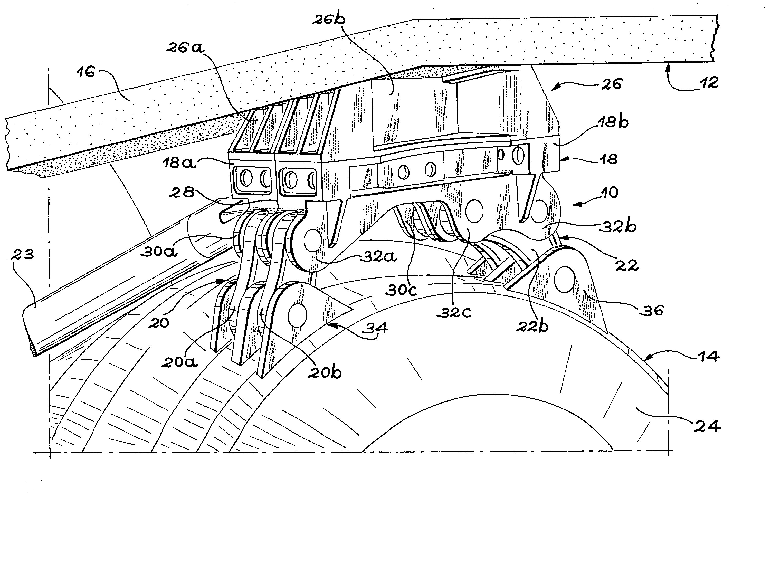
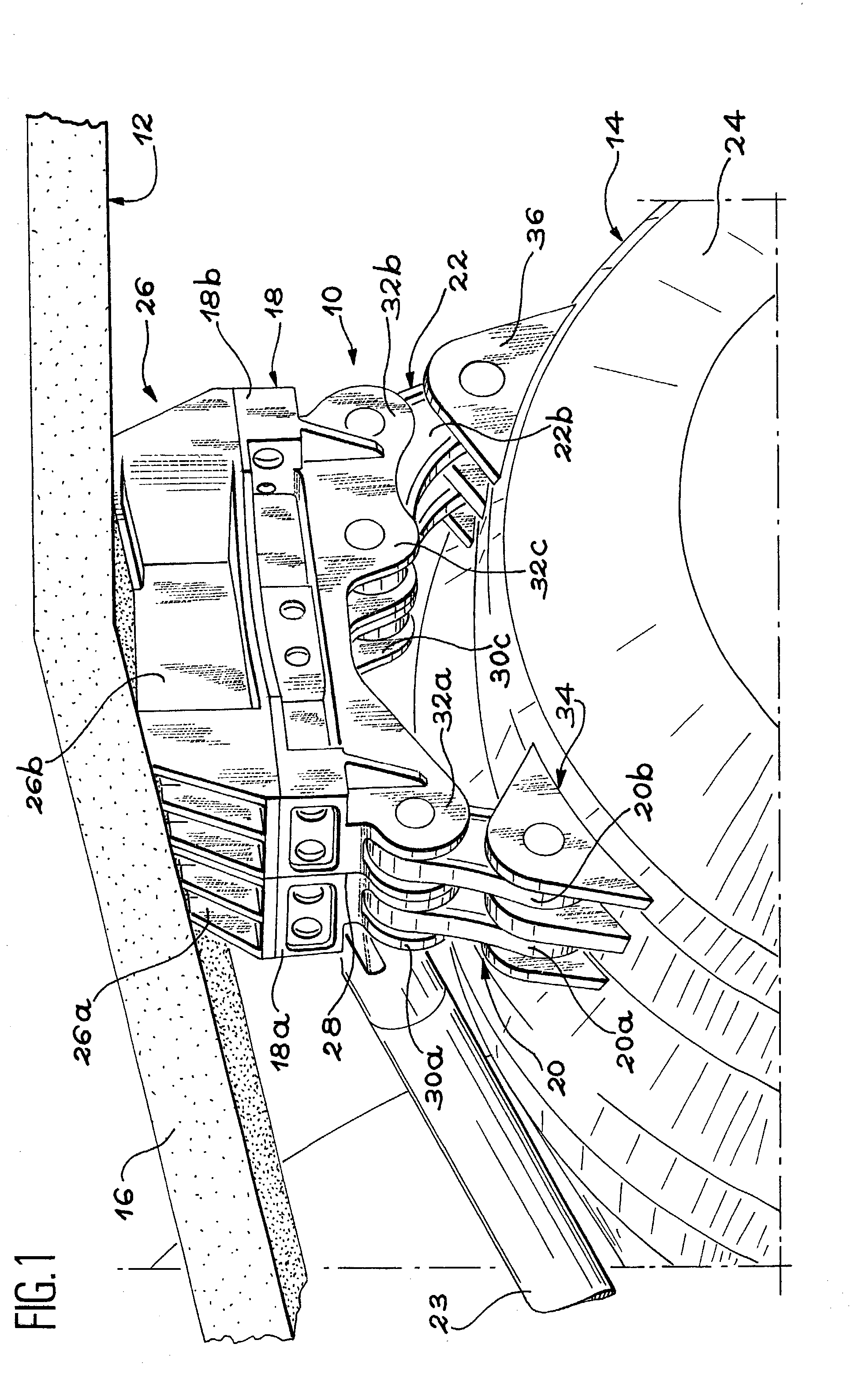
[0030] As illustrated schematically in FIG. 1, an attachment device (10) in accordance with the invention is inserted between an engine pylon (12) and an aircraft engine (14), at the front or at the rear of the said engine.

[0031] The engine pylon (12) is designed to be attached to an item of the aircraft structure, such as a section of the wing or fuselage. This attachment is provided by conventional means, which are not part of the invention. To facilitate understanding of FIG. 1, the top part of the engine pylon (12) including the means of attachment of the latter to the aircraft structure, has intentionally been omitted. More precisely, FIG. 1 simply shows the lower spar (16) of the pylon (12).

[0032] The attachment device (10) acts as an interface between the aircraft engine (14) and the engine pylon (12). More precisely, in the production method represented as an example in the figures, the function of the attachment device (10) is to take up the loads exerted in the lateral and...


PUM


Abstract

The attachment device (10) is inserted between the engine (14) and a pylon (12) designed to be attached to an aircraft structure, such as a wing or fuselage section. The attachment device (10) generally includes two brackets (18a, 18b) joined together and secured to the pylon (12) and two pairs of rods (20a, 20b, 22a, 22b) inserted between the two brackets (18a, 18b) and a part (24) of the structure of the engine (14). Thus the integrity of the link between the pylon (16) and the engine (14) is preserved in the event of failure of any of the parts which constitute the device, without there being any need for a backup attachment system.

Description

TECHNICAL BACKGROUND[0001] The invention concerns a device designed for attaching an aircraft engine to a pylon secured to a structural aircraft section such as the wing or fuselage.[0002] More precisely, the invention concerns an attachment device designed to transmit to the aircraft structure, via the engine pylon, the loads acting on the engine in the lateral and vertical directions relative to the longitudinal axis of the engine, for the case where the engine is suspended under the wing. When the engine is mounted on the side of the fuselage, the attachment device concerned by the invention, is designed to transmit the loads applied in the lateral and vertical directions in relation to the longitudinal axis of the said engine.[0003] In the remainder of the text, only the case of an engine suspended beneath an aircraft wing is described. The description below nevertheless applies also to the case of an engine mounted on the side of the fuselage, by replacing the loads acting in t...

Claims


Application Information

Patent Timeline
IPC IPC(8): B64D27/26F02C7/20
CPCB64D27/26B64D2027/266F02C7/20Y02T50/44Y02T50/671Y02T50/40Y02T50/60
Inventor LEVERT, STEPHANEROSZAK, SEBASTIEN
Owner AIRBUS OPERATIONS (SAS)
Why Eureka
Try Eureka