

Network management system
a network management system and network management technology, applied in the field of network management systems, can solve the problems of increasing the associated costs of both infrastructure and infrastructure maintenance, increasing the complexity of the management of all subscribers within the data center, and exceedingly difficult, so as to save the associated costs of implementing the vpn service and minimizing cross-configuration.
Inactive Publication Date: 2003-02-06
NEXSI SYST
View PDF20 Cites 163 Cited by
- Summary
- Abstract
- Description
- Claims
- Application Information
AI Technical Summary
Benefits of technology
[0041] In the virtualized management system of the invention, a single system administrator can configure individual devices, log servers, or services for a subscriber, the facility, or for the entire data center, all via the interface 75. In the multifunction devices described with respect to co-pending application serial number [NEXSI-01025US0], the internal management approach is to segregate individual subscribers within the multifunction device to prohibit crossover services and avoid security problems within the device itself.
[0127] More specifically, in implementing a VPN, access though a packet filtering firewall is required. In addition, static mappings in a NAT service allowing users to point a VPN client at a given address for access to the servers of the subscriber are required. In this example, a subscriber level administrator or higher can configure the parameters of the VPN via the VPN service application, by setting for example, the type of authentication used and the IP address of the VPN server, and the VPN service application will communicate with the routing, NAT and firewall applications to map the static IP, allow access to a certain port, such as port 25, for IPSec VPN traffic validation, and thereby enable the VPN for the subscriber while minimizing the cross-configuration of other services normally required in implementing a VPN.
Problems solved by technology
As the number, complexity and interaction of the services has risen, the associated costs of both the infrastructure itself and maintaining the infrastructure have risen as well.
As a result, the management of all subscribers within the data center becomes very complex and expensive with many different management interfaces for all of the subscribers and subscriber devices.
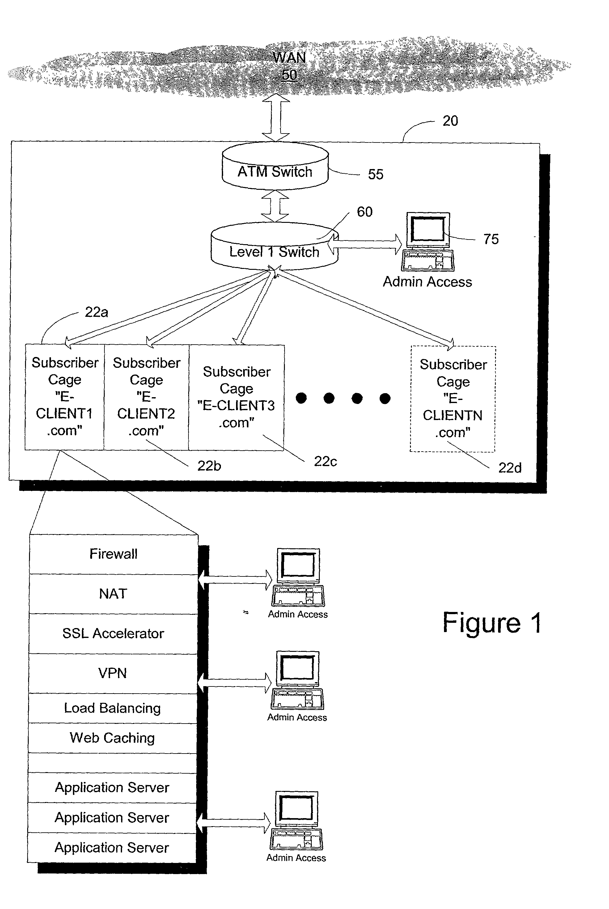
The difficulty in administering a data center as shown in FIG. 1 is that changes to each subscriber's individual configuration must be made at the cage, or at minimum, via appliance specific configuration mechanisms.
This can become exceedingly difficult where changes must physically occur at the cage or via individual devices, especially in multi-facility data canters.
However, such devices do not administer services on an object level.
That is, they do not allow the administrator access to administrative functions on a service level, but rather allow administrators to administer one or more particular types of devices via the device interface, by providing a common connection point for a number of devices in the data center.
Hence, such solutions are of limited scalability and scope.
In some cases, it may not make sense to show views and submenus.
Nevertheless, it would not make sense to launch certain types of applications in certain contexts (such as, for example, launching a certificate management application in a facility context).
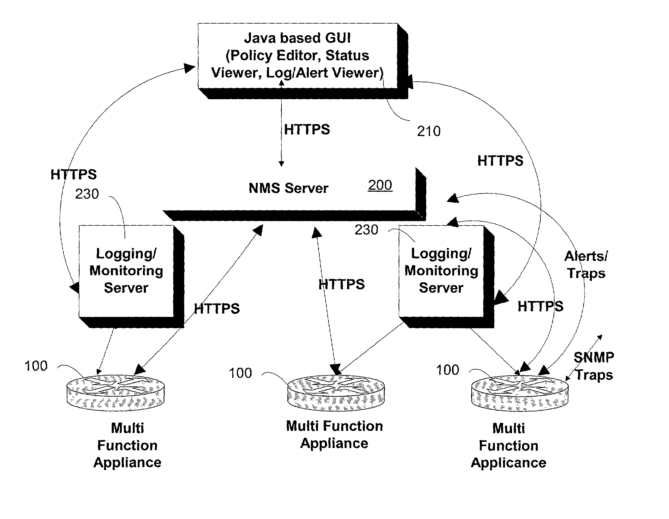
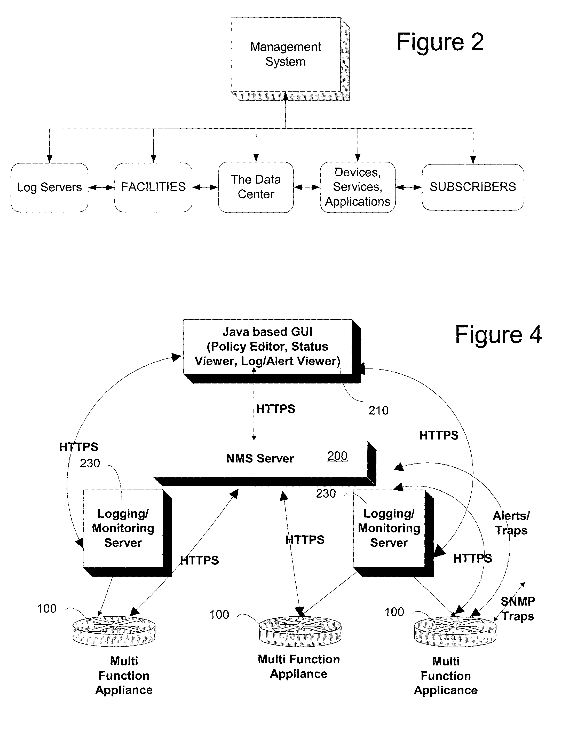
Normally because the logging function is traffic intensive, a data center may support multiple log servers to distribute the logging load.
Subscriber administrators are limited to monitoring or modifying management information that pertains only to that subscriber.
The facility administrator is limited to the management of only those objects that pertain to his / her data center facility.
This capability is potential because it is limited only by the access controls specified for this type of administrator as discussed below.
Method used
View moreImage
Smart ImageViewing Examples

Examples
Embodiment Construction
has been presented for purposes of illustration and description. It is not intended to be exhaustive or to limit the invention to the precise form disclosed. Many modifications and variations are possible in light of the above teaching. The described embodiments were chosen in order to best explain the principles of the invention and its practical application to thereby enable others skilled in the art to best utilize the invention in various embodiments and with various modifications as are suited to the particular use contemplated. It is intended that the scope of the invention be defined by the claims appended hereto.
Login to View More PUM
 Abstract
A virtual management system for a network facility, such as a data center, or any facility having a plurality of components which can be organized as objects for presentation in a virtualized environment, is disclosed. The system includes a management topology presenting devices, facilities, subscribers, log servers, and services as objects to an administrative interface; and a configuration manager implementing changes to objects in the topology responsive to configuration input from an administrator via the administrative interface. In an exemplary embodiment, the user interface is a graphical user interface designed to work in a platform independent environment. The system may include a management server coupled to the plurality of objects. In one aspect, the management server communicates with the devices, downloading configuration data to and uploading configuration data from, the devices. The management server and the interface may communicate via a LAN, WAN or the Internet.
Description
[0001] 1. Field of the Invention[0002] The present invention is directed to management of network services in a data center, and in particular to management of services, subscribers, devices, log servers, and facilities using a common, virtualized management system.[0003] 2. Description of the Related Art[0004] Public wide area networks such as the Internet have expanded the types of services used and demanded by enterprises of their network infrastructure. As the number, complexity and interaction of the services has risen, the associated costs of both the infrastructure itself and maintaining the infrastructure have risen as well. Many enterprises have turned to outsourced vendors, sometimes called a managed service provider or a data center, to provide these services in lieu of building and maintaining the infrastructure themselves. Customers of such managed service providers are called subscribers.[0005] The managed service provider can operate in many different ways. Typically ...
Claims
Login to View More Application Information
Patent Timeline
 IPC IPC(8): H04L12/24H04L29/08
CPCH04L41/0213H04L41/046H04L41/082H04L41/0856H04L41/0883H04L41/22H04L67/16H04L67/34H04L67/26H04L67/02H04L69/329H04L67/51H04L67/55H04L41/40
InventorHASAN, TAQIGANNESAN, ELANGOROCHKIND, ALLEN B.GOLLA, SAGAR
OwnerNEXSI SYST