
Method and apparatus for manufacturing minute metallic sphere

a technology of metallic spheres and manufacturing methods, applied in the direction of manufacturing tools, manufacturing apparatus, transportation and packaging, etc., can solve the problems of difficult to make the shape of particles uniform, poor yield, and the inability to avoid so-called duplex grains

Inactive Publication Date: 2003-02-13
NIPPON STEEL CORP
View PDF2 Cites 5 Cited by
  • Summary
  • Abstract
  • Description
  • Claims
  • Application Information

AI Technical Summary

Benefits of technology

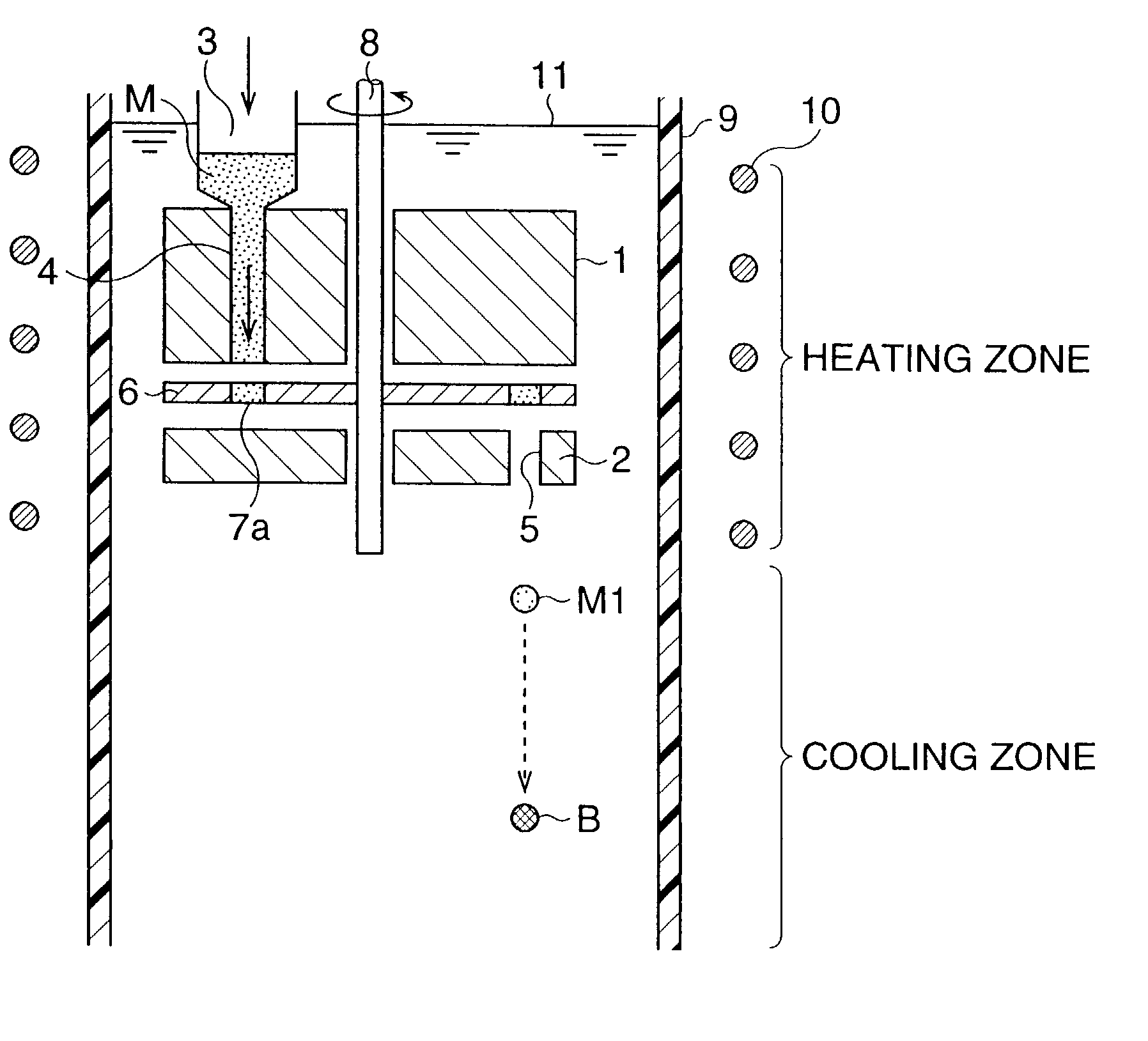
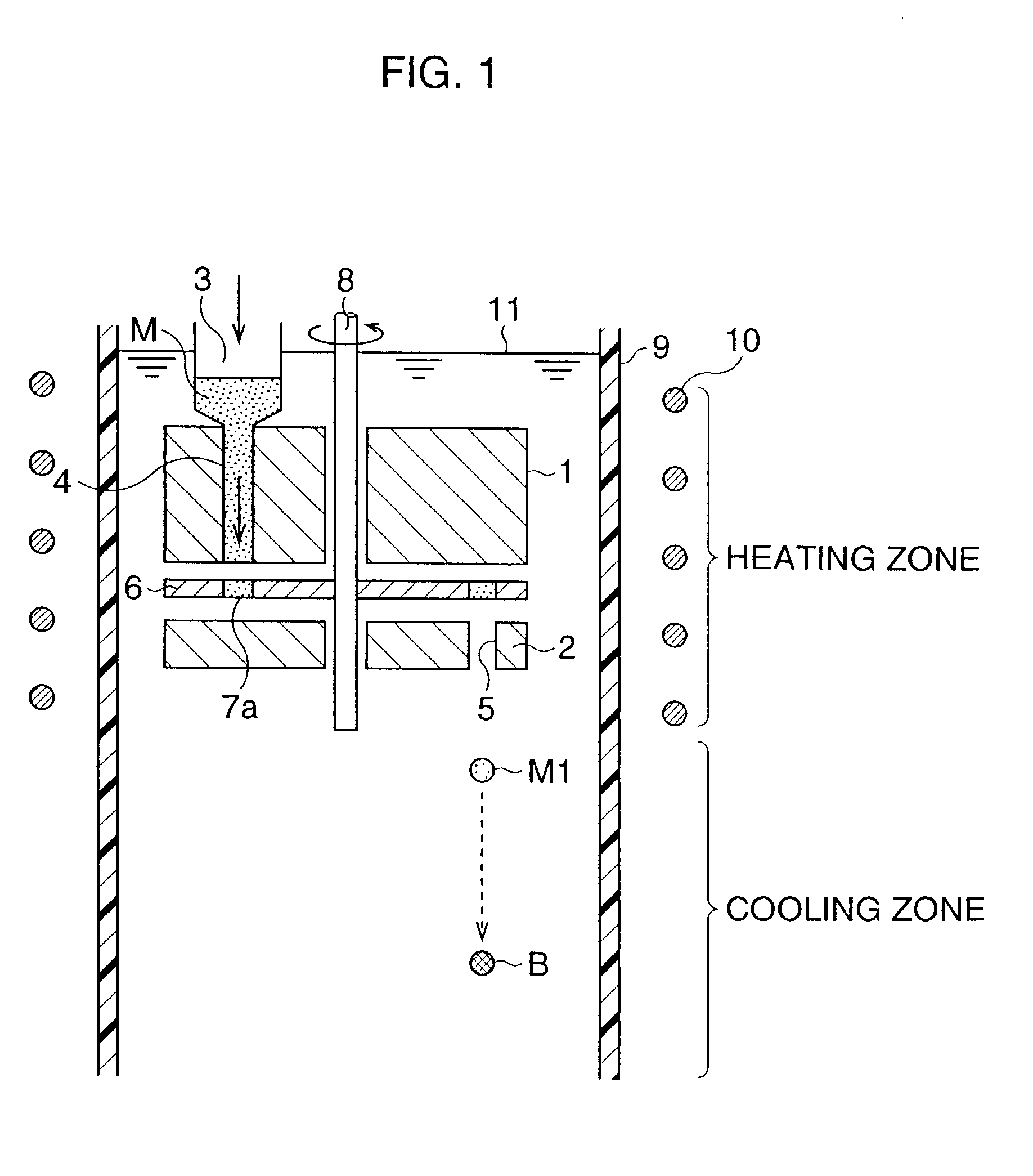
[0028] A manufacturing apparatus of minute metallic spheres of the present invention is a manufacturing apparatus of minute metallic spheres having a measurement unit in an upper portion of a vessel disposed vertically, for forming a minute metallic sphere by solidifying a molten metal discharged from this measurement unit, in a cooling medium put in the vessel, wherein the viscosity of said cooling medium is kept into 2 cSt to 20 cSt at the temperature of 200.degree. C. at which said molten metal is melted, and the dropping speed of said molten metal in said cooling medium is decreased by the viscosity of said cooling medium.
[0039] According to the present invention, by forming minute metallic spheres by the above-described manufacturing methods and apparatus, and using them for connecting a chip and a substrate in a semiconductor device, miniaturization of the package of the semiconductor device can be attained, and the cost can be lowered.

Problems solved by technology

Although a large quantity of metallic particles can be obtained for a short time by the atomization method, it is difficult to make the shapes of the particles uniform in sphere and into an aimed size, and the yield becomes very bad.
In this method, so-called duplex grain can not be avoided.

Method used


Image

  • Method and apparatus for manufacturing minute metallic sphere
  • Method and apparatus for manufacturing minute metallic sphere
  • Method and apparatus for manufacturing minute metallic sphere

Examples


first embodiment

[0100] First, the first example will be described. This example is an example of manufacturing metallic spheres having the diameter of 300 .mu.m, and corresponds to the first embodiment or the first modification.

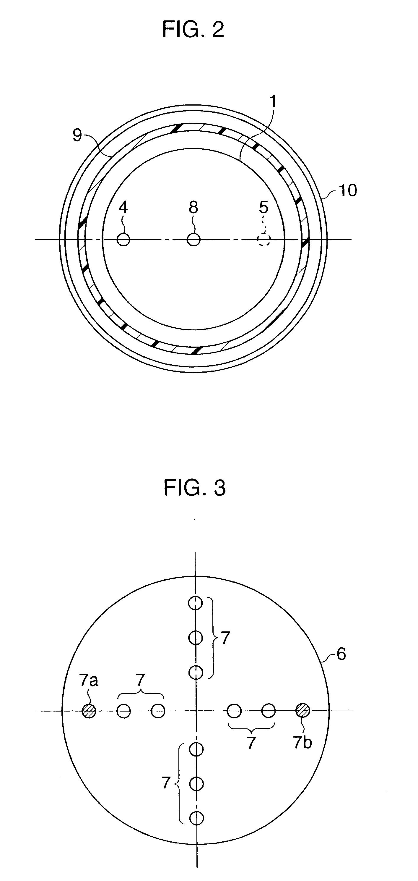
[0101] The upper portion of a vessel 9 of a cylindrical tube filled with a vegetable oil as an oil 11 is heated to 220 to 270.degree. C. by a heating coil 10. In this heating zone, a gauger 6 made of a metallic disk having the diameter of 150 mm and the thickness of 1 mm is disposed. In the guager 6, gauging portions 7 made of through holes having the diameter of 0.14 mm and formed on the circumference of the diameter of 120 mm at pitch intervals of 10 mm, are provided. The gauger 6 is set between upper and lower blocks 1 and 2, and a molten metal M is supplied and discharged in relation to the gauging portions 7 through an injection passage 4 and a discharge port 5.

1TABLE 1 heating zone yield of metallic spheres of metal composition temperature diameter of 280 to 310 .mu.m ...

second embodiment

[0107] Second Embodiment

[0108] Hereinafter, a preferred embodiment of method and apparatus for manufacturing minute metallic spheres according to the second embodiment will be described on the basis of drawings.

[0109] Here, first, a minute metallic sphere in the embodiment is an example made of, e.g., solder in particular. In manufacturing process of a semiconductor device, in order to connect an electrode portion of a semiconductor element and an external circuit or the like, both are joined through a bump made of a minute metallic sphere. This minute metallic sphere suitable for the bump is an object, and, in particular, one having a diameter size of hundreds .mu.m or less is obtained.

[0110] FIG. 6 shows an example of a schematic construction of a manufacturing apparatus of minute metallic spheres used in a method of the present invention. In FIG. 6, 31 denotes an upper block for supplying and discharging a molten metal M, 33 denotes a metal throwing-in portion, and 34 denotes an ...

third embodiment

[0150] Third Embodiment

[0151] Hereinafter, a preferred embodiment of method and apparatus for manufacturing minute metallic spheres according to the third embodiment of the present invention will be described on the basis of drawings.

[0152] Here, first, a minute metallic sphere in this embodiment is an example made of, e.g., solder in particular. In manufacturing process of a semiconductor device, in order to connect an electrode portion of a semiconductor element and an external circuit or the like, both are joined through a bump made of a minute metallic sphere. This minute metallic sphere suitable for the bump is an object, and, in particular, one having a diameter size of hundreds .mu.m or less is obtained.

[0153] FIG. 17 shows an example of a schematic construction of a manufacturing apparatus of minute metallic spheres used in a method of the present invention. In the drawing, 61 and 62 denote outer and inner blocks for supplying and discharging a molten metal M, and 63 denotes...


PUM

PropertyMeasurementUnit
specific gravityaaaaaaaaaa
temperatureaaaaaaaaaa
diameteraaaaaaaaaa

Abstract

A manufacturing method of minute metallic spheres of the present invention comprises a heating means for heating and melting a metal to form a metallic sphere, a measurement means for measuring the injected molten metal into a predetermined volume, and a cooling means for cooling the molten metal discharged from the measurement means, to a temperature less than the melting point. The measurement means has a gauger of a predetermined volume in which the molten metal is injected, and is constructed such that the molten metal is cut by rubbing by the predetermined volume by sliding this gauger in contact. The molten metal is injected in the gauger of the predetermined volume to measure, and the measured molten metal is discharged from the gauger to cool to a temperature less than the melting point, and solidified into a sphere in the cooling process.

Description

[0001] 1. Field of the Invention[0002] The present invention relates to a method and an apparatus for manufacturing minute metallic spheres suitably used for forming a ball bump on an electrode of a semiconductor device, a printed circuit board, or the like.[0003] 2. Description of the Related Art[0004] As methods of manufacturing minute metallic spheres within low-melting temparature, there are atomization method and a method of obtaining metallic spheres by dipping a metallic piece made into a predetermined volume in advance, in a heated liquid.[0005] Besides, in the method described in Japanese Patent Application Laid-open No. 4-74801, a molten metal is extruded from very fine particles in a liquid heated to a temperature more than the melting point of the metal.[0006] Although a large quantity of metallic particles can be obtained for a short time by the atomization method, it is difficult to make the shapes of the particles uniform in sphere and into an aimed size, and the yiel...

Claims


Application Information

Patent Timeline
Patent Type & Authority Applications(United States)
IPC IPC(8): B22F1/065B22F9/08B23K35/02B23K35/26H05K3/34
CPCB22F1/0048B22F9/08B22F2009/0808B22F2009/0848B22F2009/0864B22F2999/00B23K35/0244B23K35/262B23K35/268H05K3/3478B22F2203/01B22F1/065
Inventor ENDO, MICHIOTANAKA, MASAMOTO
Owner NIPPON STEEL CORP
Learn More