
Digital camera

Inactive Publication Date: 2003-02-13
XACTI CORP
View PDF5 Cites 33 Cited by
  • Summary
  • Abstract
  • Description
  • Claims
  • Application Information

AI Technical Summary

Benefits of technology

[0005] Another object of the present invention is to provide a digital camera capable of precisely adjusting focus.
[0008] The first speed is in correspondence to the above-described predetermined time period and faster than the second speed. That is, a period of the timing signal corresponding to the first speed is shorter than around of the timing signal corresponding to the second speed. Thus, a time from an input of the photographing instruction to exposure of the desired object is made shorter than a time when the timing signal is generated every period corresponding to the second speed. As a result, a responsive characteristic is improved. Furthermore, by reading the image signal of the desired object at the second speed lower than the first speed, noise included in the image signal can be reduced.
[0009] In one example of the present invention, the processing means includes an adjusting means for adjusting a photographing condition on the basis of the image signal read at the first speed, and a recording means for recording the image signal read at the second speed. Specifically, the image signal is read at the first speed when adjusting the photographing condition and whereby, the adjustment of the photographing condition is completed in a short time. On the other hand, the image signal read at the second speed, i.e., the image signal of the desired object in which noise is reduced is recorded by a recording means.
[0014] A digital camera according to the present invention comprises: an image sensor driven at a predetermined speed for photographing an object; a detecting means for detecting a high-frequency component of an image signal of the object photographed by the image sensor; an adjusting means for adjusting focus on the basis of the high-frequency component; a determining means for determining whether or not brightness of the object is enough; and a reducing means for reducing a driving speed of the image sensor when the brightness is not enough.
[0015] When the object is photographed by the image sensor, the high-frequency component of the image signal of the photographed object is detected by the detecting means. The focus is adjusted by the adjusting means on the basis of the detected high-frequency component. On the other hand, the determining means determines whether or not the brightness of the object is enough, and if the brightness is not enough, the reducing means reduces the driving speed of the image sensor.
[0016] High noise in the image signal causes high noise in the high-frequency brightness component utilized in the focus adjustment, and therefore, it is impossible to precisely adjust the focus. This is the reason why the driving speed of the image sensor is reduced when the brightness of the object is not enough. Thus, it is possible to prevent the high-frequency component from being influenced by noise, and it is possible to precisely adjust the focus.

Problems solved by technology

However, in a prior art, there is a problem that since frequency of a clock to drive the image sensor is fixed, as the frequency becomes high, high noise is included in the image signal.
Furthermore, there is a problem that the noise gives negative effect on the integrated value of the high frequency luminance component, and therefore, it is impossible to precisely adjust the focus.
On the other hand, the determining means determines whether or not the brightness of the object is enough, and if the brightness is not enough, the reducing means reduces the driving speed of the image sensor.
High noise in the image signal causes high noise in the high-frequency brightness component utilized in the focus adjustment, and therefore, it is impossible to precisely adjust the focus.

Method used


Image

  • Digital camera
  • Digital camera
  • Digital camera

Examples


Embodiment Construction

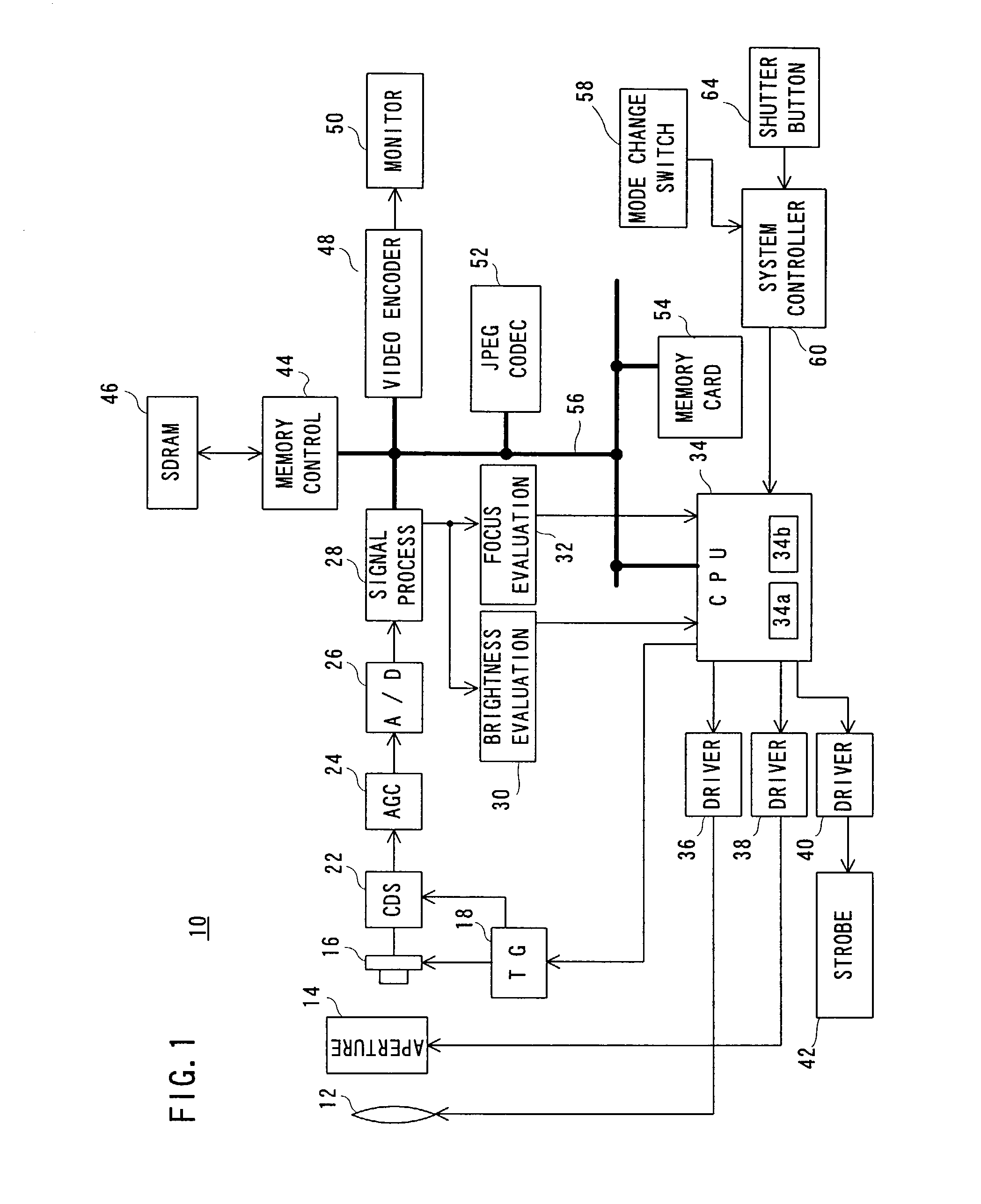
[0032] Referring to FIG. 1, a digital camera 10 of this embodiment includes a focus lens 12 and an aperture unit 14. An object image (optical image of the object) is irradiated into a CCD imager 16 of an interline transfer scheme through these members. It is noted that an effective area of the CCD imager 16 has a resolution of 640 pixels.times.480 lines (VGA) and a total number of pixels including an optical black area is 680 pixels.times.533 lines. Furthermore, a light-receiving surface of the CCD imager 16 is covered with a color filter (not shown) of a primary color Bayer array, for example.

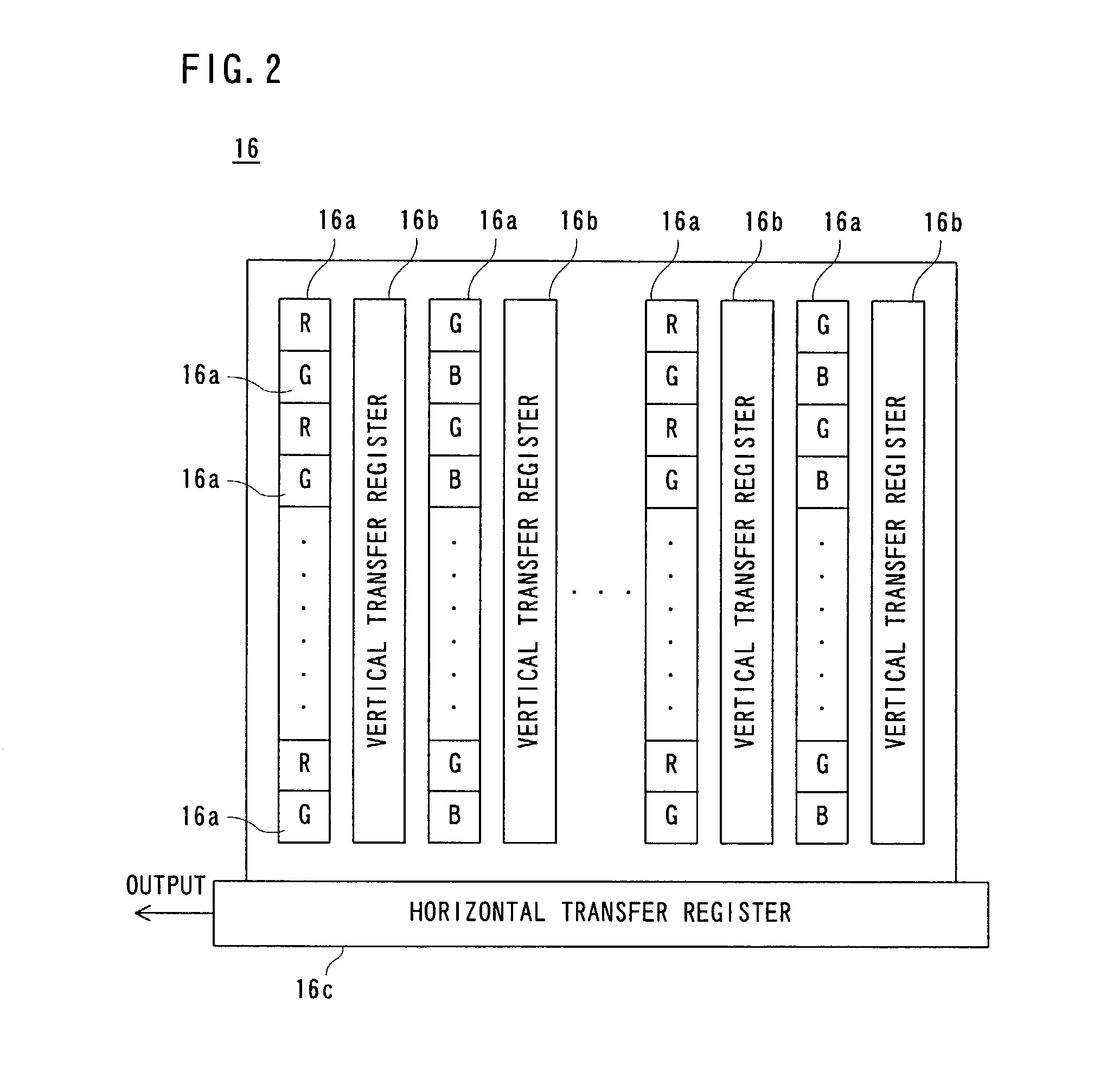
[0033] As shown in FIG. 2, the CCD imager 16 includes a plurality of light-receiving elements 16a corresponding to each of pixels, a plurality of vertical transfer registers 16b for transferring in a vertical direction an electric charge generated by photoelectronic conversion and accumulated in each light-receiving element 16a, and a horizontal register 16c arranged at an end of the vertical ...


PUM


Abstract

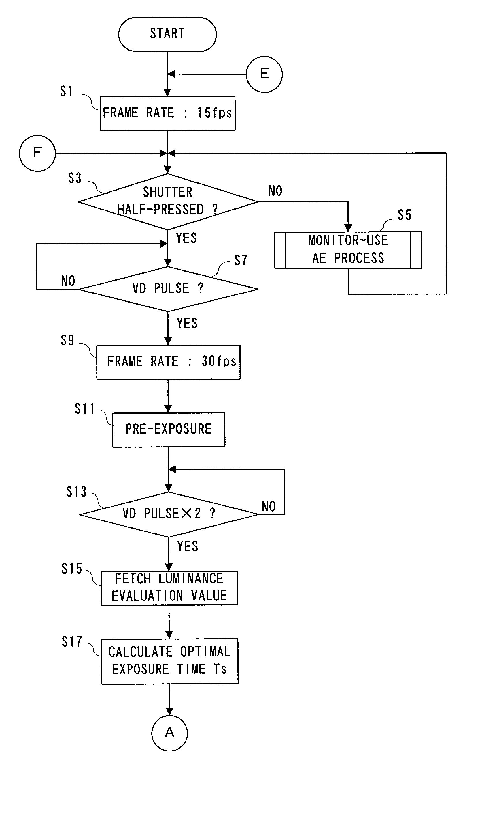
A digital camera includes a CCD imager. If brightness of an object is not enough, a frame rate of the CCD imager at a time of a focus adjustment is changed from 30 fps to 15 fps. This also lowers a reading speed of a camera signal, and reduces noise included in the camera signal. An AF evaluation value is acquired by integrating a high frequency component of a Y signal generated on the basis of the camera signal, and therefore, high noise causes an error in the AF evaluation value and fails to correctly adjust focus. This is the reason why the driving speed of the CCD imager is lowered when the brightness of the object is not enough.

Description

[0001] The present invention relates to a digital camera reading an image signal generated by a photoelectronic conversion in the image sensor therefrom.[0002] More specifically, the present invention relates to a digital camera adjusting focus on the basis of a high frequency component of an image signal corresponding to an object image photographed by an image sensor.PRIOR ART[0003] In a digital camera, an object is exposed to an image sensor such as a CCD imager, and an image signal generated by a photoelectronic conversion at a light-receiving element is read from the image sensor in response to a vertical transfer pulse and a horizontal transfer pulse. A photographing condition such as focus is adjusted on the basis of the image signal output from the image sensor. Specifically, a high frequency luminance component of the image signal is integrated, and a position of a focus lens is adjusted so that an integrated value becomes a maximum value. However, in a prior art, there is ...

Claims


Application Information

Patent Timeline
IPC IPC(8): G02B7/28G03B13/36G02B7/36H04N5/225H04N5/232H04N5/235H04N5/238H04N5/335H04N5/341H04N5/357H04N5/363H04N5/3728H04N5/378H04N101/00
CPCH04N5/23212H04N5/2353H04N23/673H04N23/73H04N23/67
Inventor TSUJINO, KAZUHIRO
Owner XACTI CORP
Learn More