Method and device for selectively emitting photons

a technology of thermophotovoltaic system and selective emitter, which is applied in the direction of semiconductor devices, basic electric elements, electrical equipment, etc., can solve the problems of reducing the conversion efficiency, and reducing the overall conversion efficiency of input heat into output electricity, so as to increase the emission of photons

Inactive Publication Date: 2003-02-20
CHARLES STARK DRAPER LABORATORY
View PDF8 Cites 13 Cited by
  • Summary
  • Abstract
  • Description
  • Claims
  • Application Information

AI Technical Summary

Benefits of technology

[0019] In one embodiment, the invention is directed to a method for converting thermal energy into photons having a wavelength within a selected wavelength range. The method includes placing a composite layer, including at least one quantum well, in thermal communication with a heat source; the composite layer having a thickness less than about 10 microns. According to one feature, the method further includes increasing emission of photons by depositing a single or multilayer antireflective coating on the composite layer. According to another feature, the method includes increasing emission of photons by depositing one or more backing layers on the composite layer. The one or more backing layers are located between the heat source and the composite layer.

Problems solved by technology

Generally, photons having too long a wavelength cannot be converted into electrical energy and can produce unwanted heat in the converter, thereby reducing the overall conversion efficiency of input heat into output electricity.
Photons with too short a wavelength generate electricity in the converter, but these short wavelength photons also generate excess energy that is converted into heat inside the converter and thus lower conversion efficiency.
As discussed above, the conversion efficiency of prior art TPV systems is poor because of the high percentage of substantially unusable light present in the emitter spectrum.
The selectivity ratio is also limited by the properties of any selective filters used and by the optical-line structure (thermally broadened) of the selective emitter.
Increasing the emitter thickness can increase average emittance, however, the increased thickness may also increase the unwanted long-wavelength emittance more than the desired emittance.
As a result, metallic emittance is generally low.
Despite the selectivity ratio, long-wavelength light over a large range reduces prior art TPV system efficiency.
Selective filters, however, have disadvantages.
Thus, while the selective filters are helpful in removing some of the photons having a wavelength not suitable for generating electricity in the converter, they are not as useful as could be desired, particularly for low-temperature-emitter sources.
Antenna filters, however, are expensive and they still transmit a significant portion of the unwanted long-wavelength light and block useful light.

Method used


Image

  • Method and device for selectively emitting photons
  • Method and device for selectively emitting photons
  • Method and device for selectively emitting photons

Examples


Embodiment Construction

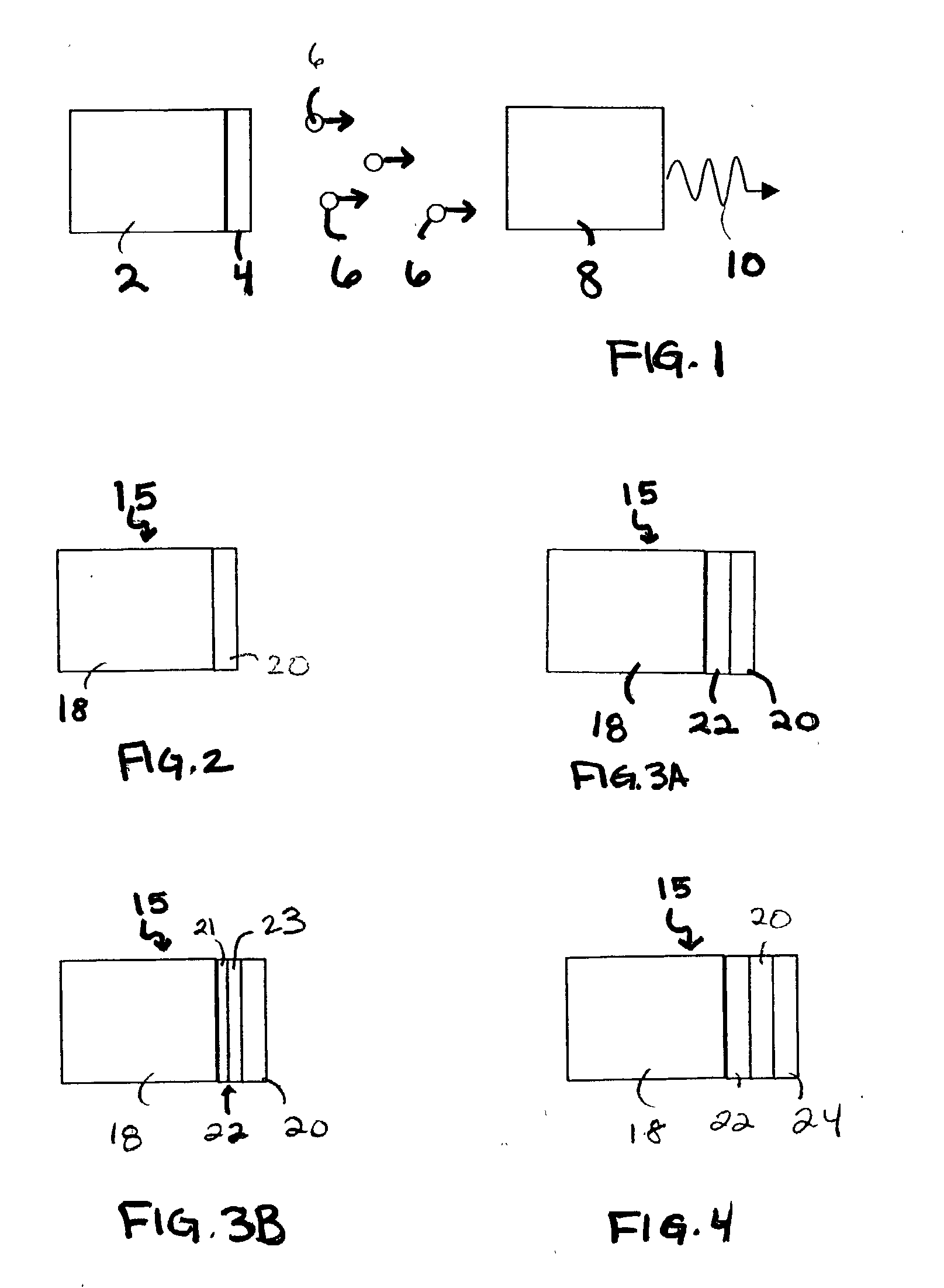
[0050] Thermophotovoltaic (TPV) systems convert thermal energy to electric energy. As shown in FIG. 1, a TPV system typically includes a heat source 2, an emitter 4 in thermal communication with the heat source 2, and a photovoltaic converter 8. The heat source 2 provides thermal energy to the emitter 4, which emits photons 6 in response. The photovoltaic converter 8 collects and converts some of these photons 6 into electric energy 10.

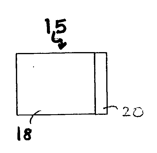
[0051] The invention, in one embodiment, is directed to emitters for TPV systems. An emitter, according to the present invention, emits photons having a selected wavelength that is suitable for conversion into electrical energy by a photovoltaic converter 8 (e.g., a wavelength within a wavelength range, such as from about 1.2 microns to about 1.5 microns, or from about 1.5 microns to about 2 microns). In general, the emitter of the invention includes a thin layer of a semiconductor material in physical or radiant contact with a heat source. Depending ...


PUM


Abstract

A selective emitter for a thermophotovoltaic system includes a heat source and a semiconductor layer having a thickness less than about 10 microns in thermal communication with the heat source. The heat source provides thermal energy to the semiconductor layer, which emits photons having a selected wavelength that is suitable for conversion into electrical energy by a thermophotovoltaic converter, in response to receiving thermal energy.

Description

REFERENCE TO RELATED APPLICATIONS[0001] This application claims the benefit of U.S. Provisional Patent Application Serial No. 60 / 312,198, filed on Aug. 14, 2001, and entitled "Method And Device For Selectively Emitting Photons," the entire contents of which are incorporated by reference herein.[0002] The invention relates to devices and methods for selectively emitting photons. In particular, in one embodiment, the invention relates to combining a semiconductor layer with a heat source for converting thermally excited electronic motion into photons of a selective wavelength.[0003] Thermophotovoltaic (TPV) converters convert photons to electrical energy. Generally, a TPV system includes a heat source, an emitter, and a converter. The emitter, through physical (or radiant) contact with the heat source, is heated and then converts thermally excited electrons into photons. These photons are then transmitted to, and converted into electrical energy via, the converter. The efficiency of t...

Claims


Application Information

Patent Timeline
Patent Type & Authority Applications(United States)
IPC IPC(8): H01L33/00
CPCH01L33/0004
Inventor MEULENBERG, ANDREW JR.
Owner CHARLES STARK DRAPER LABORATORY
Why Eureka
Try Eureka