
Image processing apparatus having rewritable firmware, job management method, and management apparatus

a management apparatus and image processing technology, applied in the direction of program control, digital output to print units, instruments, etc., can solve the problems of insufficient optimization of the internal control unit in the image processing apparatus for completing the firmware rewriting quickly, the processing of such large firmware takes several tens of minutes, and the complexity of the mask rom exchang

Active Publication Date: 2003-02-20
MINOLTA CO LTD
View PDF3 Cites 53 Cited by
  • Summary
  • Abstract
  • Description
  • Claims
  • Application Information

AI Technical Summary

Benefits of technology

[0017] In addition, a third object of the present invention is to provide a management apparatus that is connected to an image processing apparatus and that coordinates image processing job execution requests from users and the necessity of firmware rewriting, and is capable of adequately performing job management for the image processing apparatus.
[0019] Accordingly, it is possible to rationally modify an execution schedule of received image processing jobs and received firmware rewriting jobs, based on predetermined conditions, and the execution schedule can be determined with sufficient consideration for both a firmware rewriting demand and an image processing job demand.
[0024] According to the stated structure, firmware rewriting can be given priority to a degree that does not inconvenience a user who has issued a print job.
[0030] By having an urgent firmware rewriting job executed with priority, problems in the image processing apparatus can be prevented before they occur, and image processing jobs can be executed in a optimum state. This is of benefit to the user.
[0040] By including a modifying unit, the management apparatus is able to modify the execution schedule of image processing jobs and firmware rewriting jobs rationally. Furthermore, the management unit is able to manage jobs for the image processing apparatus with sufficient consideration to firmware rewriting demands and image processing job execution demands.

Problems solved by technology

This is costly since exchanging the mask ROMs is complicated and takes considerable effort.
Due to cost demands, the structure of the internal control unit in an image processing apparatus is not optimized for completing the firmware rewriting quickly, since the firmware in an image processing apparatus is not rewritten often.
For this reason, processing for rewriting such large firmware takes several tens of minutes.
Furthermore, while the firmware of a control module that executes print control is being rewritten, print control cannot be executed, and therefore print jobs are not executed during this time.
However, this kind of redundant structure is generally not feasible because of restrictions in cost of the image forming apparatus.
Having jobs executed in order of reception as described above can cause, for example, the following types of inconveniences.
Considering that the time required to rewrite the firmware as described above may be several tens of minutes, this causes inconvenience for the user who has to wait for several tens of minutes, and also hinders smooth paperwork.
In such cases, there is a danger that waiting until after all print jobs that were received before the firmware rewriting job have ended to execute rewriting processing may result in print defects such as deterioration of printed image quality, or jams.
3. Furthermore, having the execution schedule of jobs determined at the discretion of the image processing apparatus can be contrary to the wishes of the user.
Such problems in a firmware rewriting system occur not only in image forming apparatuses such as printers and photocopiers, but also in scanners or in image data processing apparatuses (hereinafter apparatuses that are involved in some way with processing image data are referred to under a broader term "image processing apparatuses").
Furthermore, the "second sender" is, for example, is a client terminal that is connected to the image processing apparatus, and that issues image processing jobs to the image processing apparatus.

Method used


Image

  • Image processing apparatus having rewritable firmware, job management method, and management apparatus
  • Image processing apparatus having rewritable firmware, job management method, and management apparatus
  • Image processing apparatus having rewritable firmware, job management method, and management apparatus

Examples


first embodiment

[0076] First Embodiment

[0077]

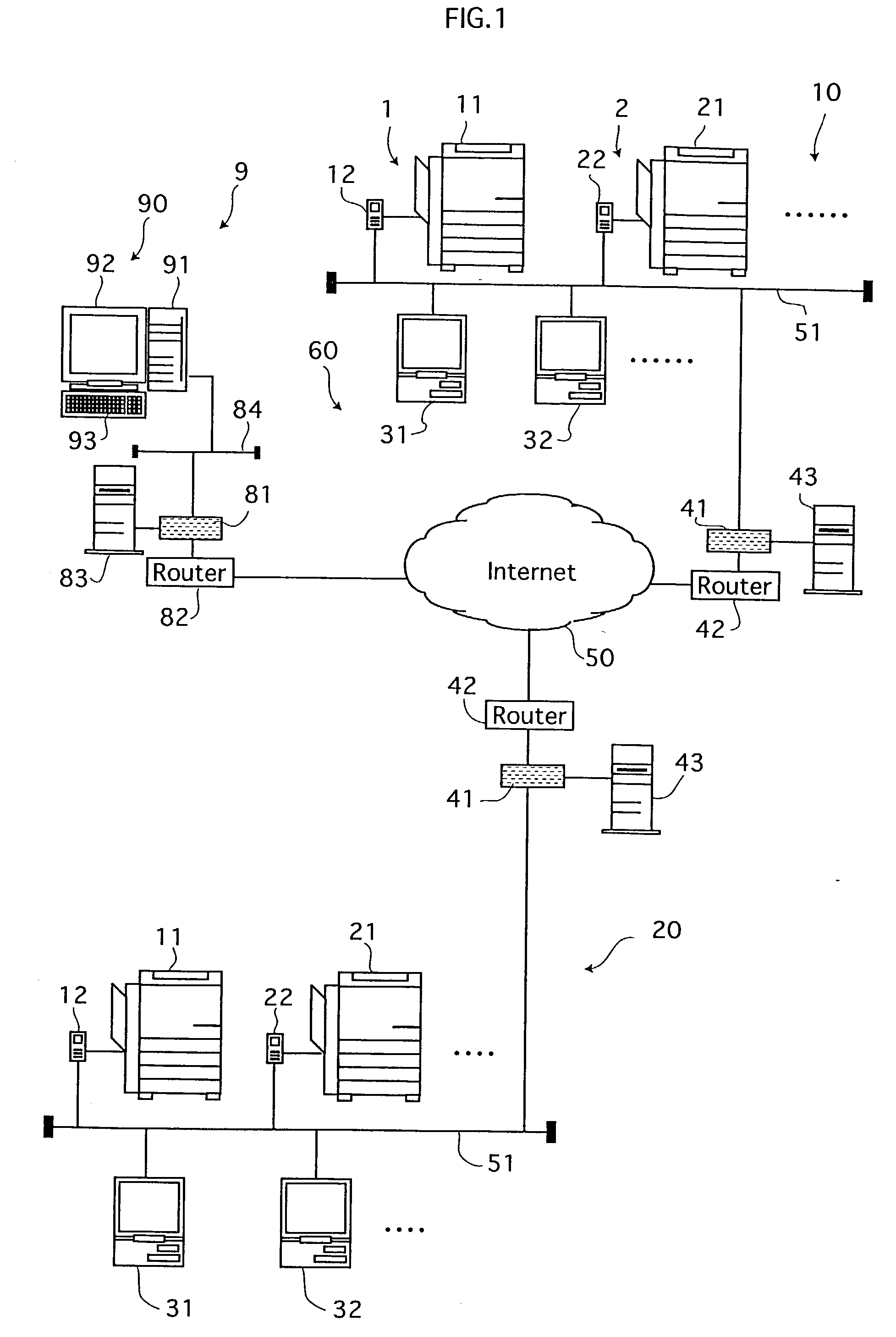
[0078] FIG. 1 shows the structure of an image processing system (hereinafter simply referred to as "system") that includes the image processing apparatus of the present embodiment.

[0079] As the figure shows, the system is composed of a PC (personal computer) 90 that is in a service center 9 and that manages firmware, an apparatus group 10 that is in a user's office or the like and that includes image processing apparatuses 1, 2, etc. and client terminals 31, 32, etc. The PC 90 and the apparatus group 10 are connected here by the Internet 50. In addition, an apparatus group 20 owned by another user is also connected to the Internet 50. Transmission and reception of various types of data such as image data is possible between the apparatuses via the Internet.

[0080] In the present embodiment firmware denotes programs that are for controlling hardware devices, and that are basic software executed by the modules (described later) in the image processing appa...

second embodiment

[0237] Second Embodiment

[0238] In the first embodiment execution of print jobs is always given priority over execution of firmware jobs. However, there are cases in which firmware rewriting processing is executed before print job processing because the time required for the rewriting processing is short and therefore does not cause significant delays in the print job processing. Accordingly, a feature of the present embodiment is that the time necessary to execute a firmware rewriting job is found, and the execution order of jobs altered according to the length of the rewriting job.

[0239] Consequently, the structures of the apparatuses and so on are the same as those in the first embodiment, while the job management control content differs. The following description focuses on the aspects of the second embodiment that differ from the first.

[0240] FIG. 17 is a flowchart showing an e-mail downloading processing (see FIG. 11, step S111) sub-routine in the present embodiment. Steps numb...

third embodiment

[0269] Third Embodiment

[0270] The following described a third embodiment with reference to FIGS. 21 to 23.

[0271] In the third embodiment, the processing for downloading e-mail at step S111 and the content of the job transmission processing at step S114 in FIG. 11 differ to some extent to the second embodiment.

[0272] Specifically, in the e-mail downloading processing in the second embodiment, the firmware expected rewriting time is compared with a predetermined time when determining the position in the job management table 211 in which to register the firmware rewriting job (FIG. 17, step S152). However, in the present embodiment, the firmware expected rewriting time is compared to a processing time of the total print data of unprocessed print jobs, to determined the execution order.

[0273] In FIG. 21, the CPU 201 first executes processing to download newly received e-mail and so on (steps S121 to S130), then calculates the print data expected processing time and the firmware (FW) exp...


PUM


Abstract

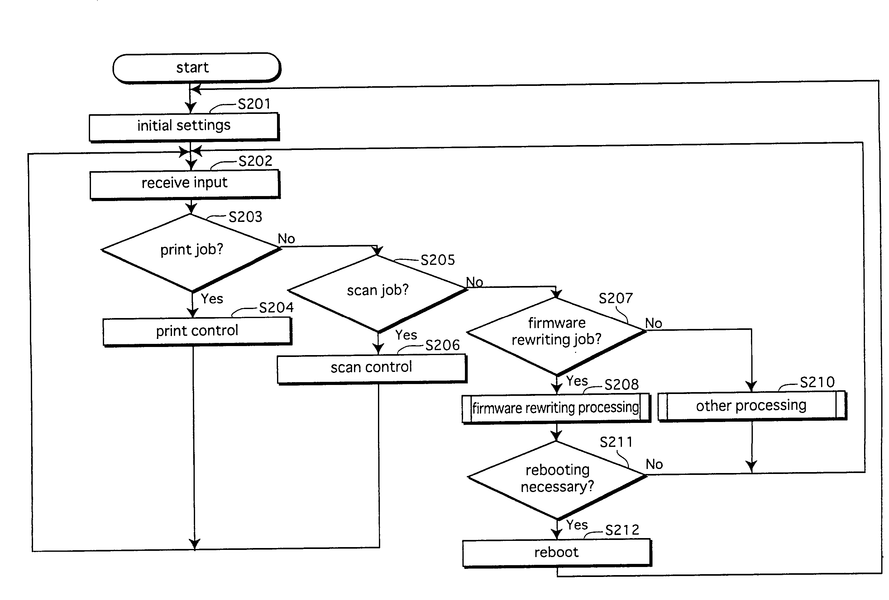
A printer controller receives firmware attached to e-mail from a mail server, downloads the firmware to an internal hard disk drive, and registers the job at the bottom of a job registration table. On subsequently receiving a print job or a scan job, the printer controller registers the job in the job management table, judges whether a firmware rewriting job is registered in the job management table, and if so, moves the print job or the scan job to be before the firmware rewriting job in the job management table. In this way, firmware rewriting jobs are always executed after print jobs, meaning that processing of print jobs is not delayed.

Description

[0001] This application is based on application No. 2001-249600, filed in Japan, the contents of which are hereby incorporated by reference.[0002] (1) Field of the Invention[0003] The present invention relates to an image processing apparatus and a management apparatus that are connected to a client terminal, and in particular to a technique for determining a schedule for executing image processing jobs and firmware rewriting jobs in the image processing apparatus.[0004] (2) Related Art[0005] Conventionally, when there is a need to change programs or control parameters for controlling operations of an image forming apparatus such as a printer, the mask ROM on the control circuit board in the image forming apparatus is exchanged for a mask ROM in which new firmware is written. However, it is necessary to send a service person out to exchange the mask ROM. This is costly since exchanging the mask ROMs is complicated and takes considerable effort.[0006] For this reason, systems have be...

Claims


Application Information

Patent Timeline
IPC IPC(8): G06F3/12G06F11/00B41J29/38H04N1/00
CPCH04N1/00204H04N1/00915H04N1/00973H04N2201/0039
Inventor TOMITA, ATSUSHIHINO, HIDEKIMAE, HIDEO
Owner MINOLTA CO LTD
Learn More