

Spiral gas flow plasma reactor
Inactive Publication Date: 2003-03-13
CERAMOPTEC IND INC
View PDF4 Cites 4 Cited by
- Summary
- Abstract
- Description
- Claims
- Application Information
AI Technical Summary
Benefits of technology
[0014] It is another object of this invention to provide a method capable of producing a spiral flow of precursor gas that results in a particularly stable plasma, resulting in a homogeneous deposition of a desired thickness over a large substrate surface area.
[0015] It is yet another object of this invention to provide a device capable of producing a spiral flow of precursor gas that results in a particularly stable plasma, resulting in a homogeneous deposition of a desired thickness over a large substrate surface area.
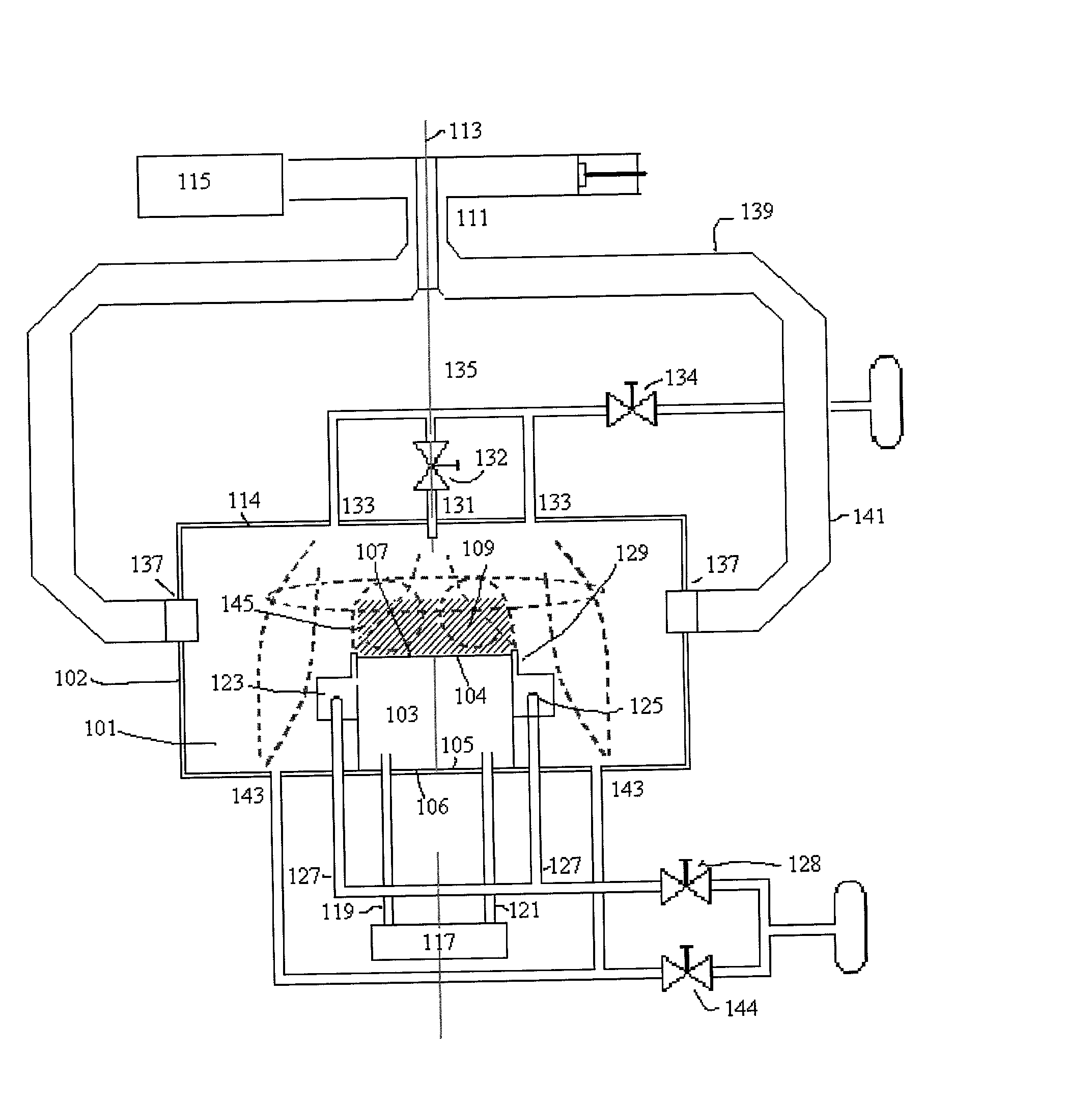
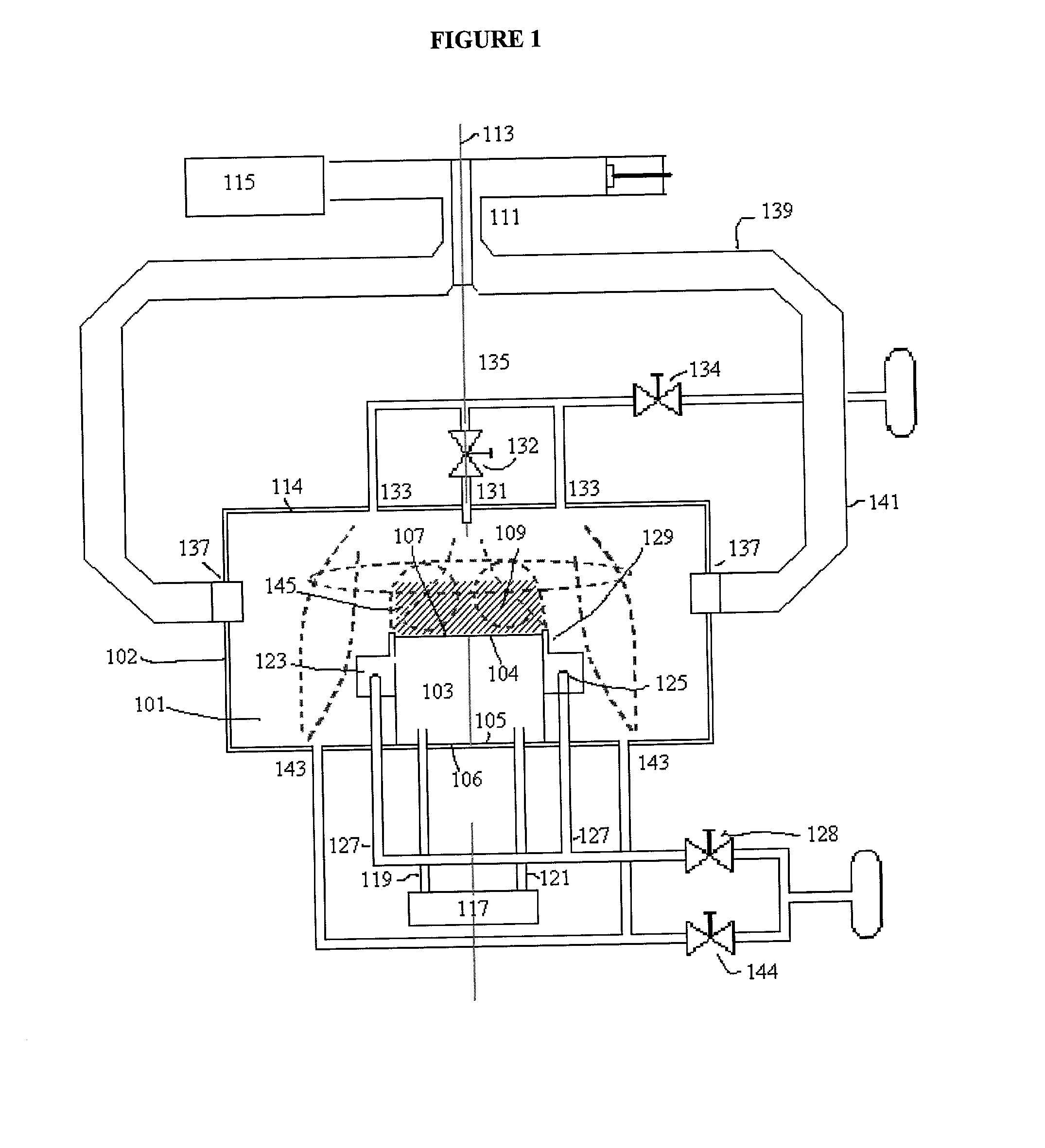
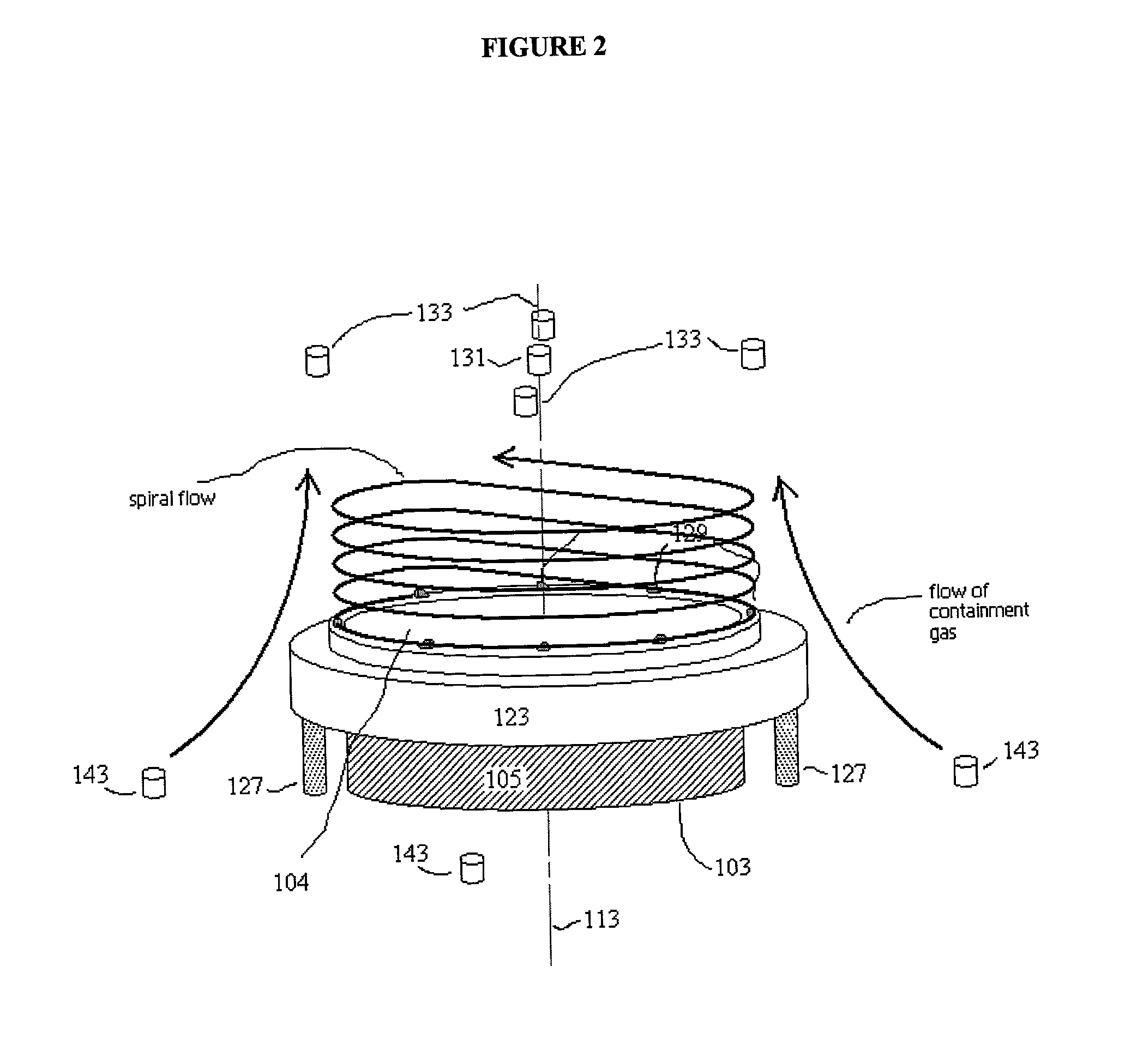
[0016] Briefly stated, the present invention provides a plasma reactor for thin film deposition and an accompanying method. The reactor comprises a system of input means and exhaust means that produce an adjustable spiral flow of precursor gas used in creating a spatially stable plasma over large substrate surface areas. The flow of gas created by this configuration of input and exhaust means results in a plasma that remains uniform as it extends radially from the center to the edges of the substrate and is capable of high quality depositions and high deposition rates. In a preferred embodiment, the input means is in the form of a ring jet with a tangential flow component surrounding the substrate. Gas exhausts through exhaust means located at a preselected distance above the substrate. In a preferred embodiment, gas exhausts through a central exhaust aperture and a number of surrounding apertures located at a preselected distance from the central exhaust aperture. Both the central and surrounding exhaust apertures may be connected by an adjustable manifold to allow for coordinated positioning of the central and surrounding apertures. Additionally, apertures located at the bottom of the cavity can be used to input additional precursor gas so as to maintain the spiral flow over the substrate.
Problems solved by technology
Present plasma reactors suffer from a number of significant problems.
Present plasma reactors require that the chamber be relatively small, requiring complex cooling systems.
Also, the resultant plasmas are often uneven due to difficulty in maintaining a uniform density in a plasma as it extends from the center of the substrate, and thus cause uneven deposition rates and thicknesses on the substrate.
Present radio frequency plasma reactors, because of lower frequencies and size, often are of a density insufficient for current processing requirements.
Therefore, the size of a processable substrate is limited, and it usually does not exceed an area with a diameter of 100 mm.
This results in a plasma of non-uniform density and deposition rates in the area above the substrate.
This configuration limits control of the gas flow to modifications in the volume of gas inputted or exhausted, leaving the operator little ability to change or limit the path of the gas flow to affect the uniformity and thickness of the deposition.
Potential problems still exist with this application due to the complexity of the configuration of the apparatus and the substrate, and can result in potential inconsistencies in deposition thickness.
Another problem with this apparatus is that it may only be suitable for flat rectangular surfaces.
Its primary deficiency is its inability to uniformly coat large flat substrates.
The physical geometry of such ball plasmas results in a decrease in electric field intensity and resulting deposition thickness with increasing distance from the substrate center.
Thus, these applications also suffer from the inability to create uniform deposition over large substrate areas.
Method used
View moreImage
Smart ImageViewing Examples

Examples
example 2
[0042]
2 Diamante film deposition Substrate diameter: 150 mm Pressure: 60 mbar Rotated gas flow through jet 129: 8 liters / min Axial gas flow through apertures 143: 3 liters / min Pumped flow through aperture 131: 20% Pumped flow through apertures 133: 80%
Login to View More PUM
| Property | Measurement | Unit |
|---|---|---|
| Flow rate | aaaaa | aaaaa |
| Ratio | aaaaa | aaaaa |
| Distance | aaaaa | aaaaa |
Abstract
A plasma reactor and accompanying method for thin film deposition is disclosed, comprising a system of input means and exhaust means that produce an adjustable spiral flow of precursor gas used in creating a spatially stable plasma over large substrate surface areas. The flow of gas created by this configuration of input and exhaust means results in a plasma that remains uniform as it extends radially from the center to the edges of the substrate and is capable of high quality depositions and high deposition rates. In a preferred embodiment, the input means is in the form of a ring jet with a tangential flow component surrounding the substrate. Gas exhausts through exhaust means located at a preselected distance above the substrate. In a preferred embodiment, gas exhausts through a central exhaust aperture and a number of surrounding apertures located at a preselected distance from the central exhaust aperture. Both the central and surrounding exhaust apertures may be connected by an adjustable manifold to allow for coordinated positioning of the central and surrounding apertures. Additionally, apertures located at the bottom of the cavity can be used to input additional precursor gas so as to maintain the spiral flow over the substrate.
Description
[0001] 1. Field of the Invention[0002] The invention concerns plasma reactors for use in commercial processes of film deposition, etching and other processing of large surfaces of a substrate.[0003] 2. Information Disclosure Statement[0004] Plasmas are useful in many processes, including surface processing and film deposition. Plasma Enhanced Chemical Vapor Deposition (PECVD) is a useful and effective method for thin film deposition. Radio Frequency PECVD, in which radio frequency energy between 3 and 30 MHz is used to strike the plasma, is useful for deposition of silicon-based films. Microwave assisted PECVD of diamond and diamond-like films offers the ability to produce uniform films over larger substrate areas than hot filament CVD. Microwave assisted PECVD is also more suitable than hot filament CVD for high purity applications. Microwave plasma discharge is best achieved when using precursor gas in low pressure environments (less than 100 mm of Hg), as only then is it possible...
Claims
Login to View More Application Information
Patent Timeline
 IPC IPC(8): C23C16/44C23C16/455C23C16/511H01J37/32
CPCC23C16/455C23C16/45502C23C16/511H01J37/3244H01J37/32834
InventorNEUBERGER, WOLFGANGSOLOMATINE, ALEXEI
OwnerCERAMOPTEC IND INC