Sputtering target and/or coil, and process for producing same

a technology of sputtering target and coil, which is applied in the direction of diaphragms, metal-working apparatus, metallic material coating processes, etc., can solve the problems of unsatisfactory vacuum degree, inability to solve countermeasures against unsatisfactory vacuum degree, and inability to reduce the volume of hydrogen in conventional mechanical processing. , to achieve the effect of reducing adsorption or occlusion of hydrogen, increasing vacuum, and uniform and fine structures

Active Publication Date: 2018-04-24
JX NIPPON MINING & METALS CORP
View PDF23 Cites 0 Cited by
  • Summary
  • Abstract
  • Description
  • Claims
  • Application Information

AI Technical Summary

Benefits of technology

[0046]For the need of reducing the volume of the adsorbed or occluded hydrogen, it has been found that heating of the surface of the target and / or the coil before being installed in a sputtering apparatus (vacuum chamber) is effective. Thus, provided is a sputtering target and / or a coil that reduces adsorption or occlusion of hydrogen to the target surface, enhances the degree of vacuum during sputtering, has a uniform and fine structure, gives stable plasma, and allows production of a film having excellent uniformity, and also provided is a method of producing the target and / or the coil.
[0048]In order to solve the above-described problems, the present invention is based on the findings that heating of a sputtering target and / or a coil disposed at the periphery of a plasma-generating region for confining plasma under a vacuum atmosphere or an inert gas atmosphere is effective.
[0059]In the present invention, heating of a target and / or a coil is effective in the process of producing the target and / or the coil, in particular, before installation in a sputtering apparatus (vacuum chamber). This can provide the sputtering target and / or coil which have effects of reducing adsorption or occlusion of hydrogen to the surface of the target, increasing the degree of vacuum during sputtering, providing uniform and fine structures, giving stable plasma, and allowing production of a film having excellent uniformity.

Problems solved by technology

However, there was a problem in sputtering the target that the degree of vacuum in a vacuum chamber does not increase.
As long as based on this idea, a countermeasure against the problem of an unsatisfactory degree of vacuum could not be solved.
That is, the volume of hydrogen could not be necessarily reduced in conventional mechanical processing of the surfaces of a target and a coil.
However, the problem is understood as only an issue of the composition of the target.
Thus it does not provide a fundamental solution for the problem that the degree of vacuum in a vacuum chamber is not enhanced.
And there is a problem that how the volume of hydrogen is decreased during processing of a target is not technically disclosed or suggested.
However, in this case also, the problem is understood as only an issue of the composition of a target.
Thus it does not provide a fundamental solution for the problem that the degree of vacuum in a vacuum chamber is not enhanced.
And there is a problem that how the volume of hydrogen is decreased during processing of a target is not technically disclosed or suggested.
Patent Literature 4 discloses that the oxygen content is 150 ppm or less, that oxygen is generated during sputtering to disadvantageously affect the film characteristics such as a resistance value of the film to be formed, and that a decrease in the number of generated particles and a decrease in oxygen content conflict with each other.
Thus it does not provide a fundamental solution for the problem that the degree of vacuum in a vacuum chamber is not enhanced.
And there is a problem that how the volume of hydrogen is decreased during processing of a target is not technically disclosed or suggested.
This is not understood as only a problem of hydrogen, but understood as an issue of the composition of a target; thus it does not provide a fundamental solution for the problem that the degree of vacuum in a vacuum chamber is not enhanced.
And there is a problem that how the volume of hydrogen is decreased during processing of a target is not technically disclosed or suggested.
However, it does not provide a fundamental solution for the problem that the degree of vacuum in a vacuum chamber is not enhanced.
And there is a problem that how the volume of hydrogen is decreased during processing of a target is not technically disclosed or suggested.
This case also does not provide a fundamental solution for the problem that the degree of vacuum in a vacuum chamber is not enhanced.
And there is a problem that how the volume of hydrogen is decreased during processing of a target is not technically disclosed or suggested.
However, this case also does not provide a fundamental solution for the problem that the degree of vacuum in a vacuum chamber is not enhanced.
And there is a problem that how the volume of hydrogen is decreased during processing of a target is not technically disclosed or suggested.
The other is that it is necessary to reduce the volume of hydrogen and moisture adsorbed, occluded, or solid-solubilized in the vacuum container and the device, since a sufficient acceleration cannot be achieved if hydrogen is occluded or solid-solubilized in the member in a device such as an accelerating cavity.
In that sense, when inclusion of hydrogen or moisture is a problem, it is necessary to reduce the volume of hydrogen or moisture of the entire target (the entire area to be eroded), and the idea that merely mechanical polishing of the surface can solve the problem is not conceivable.
Since the device and equipment are used for a relatively long time after the conduction of the process, it is hardly conceivable that the process is applicable to a sputtering target which is frequently replaced.
However, this is merely preventing the function of the hydrogen-occluding metal temporarily.
In this sense, when inclusion of hydrogen or moisture is a problem, it is necessary to reduce the volume of hydrogen or moisture of the entire target (the entire area to be eroded), and the idea that merely mechanical polishing of the surface can solve the problem is not conceivable.
However, the sputtering target, which thereafter is used for a long time with repetition of occlusion and release of hydrogen, it is hardly conceivable that the process is applicable to a sputtering target which is frequently replaced.

Method used


Image

  • Sputtering target and/or coil, and process for producing same
  • Sputtering target and/or coil, and process for producing same

Examples


example 1

[0089]A tantalum raw material having a purity of 99.997% was molten by an electron beam and was cast into an ingot or billet having a thickness of 200 mm and a diameter of 200 mm. Subsequently, this ingot or billet was drawn at room temperature and then was subjected to recrystallization annealing at 1500K to obtain a material having a thickness of 100 mm and a diameter of 100 mm.

[0090]The resulting material was subjected to cold drawing, upset forging, and recrystallization annealing at 1173K. Subsequently, a cold rolling was performed again and a process of annealing at 1173K (900° C.) was repeated twice. After finishing processing, a target material having a thickness of 10 mm and a diameter of 320 mm was obtained.

[0091]The target prepared as above was adjusted the surface roughness by finishing processing, and dehydrogenation thereof was performed in the following conditions:

[0092]Surface roughness of the target: 0.2 μm

[0093]Heating conditions of the target: vacuum atmosphere, a...

example 2

[0096]A target material prepared in the same conditions as those in Example 1 was adjusted the surface roughness by finishing processing, and dehydrogenation thereof was performed in the following conditions:

[0097]Surface roughness of the target: 0.2 μm

[0098]Heating conditions of the target: vacuum atmosphere, a temperature of 700° C., for 2 hours.

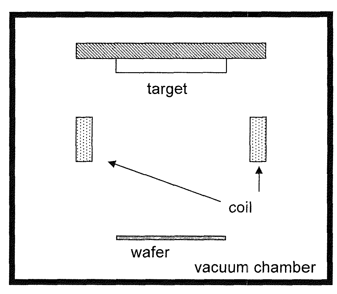
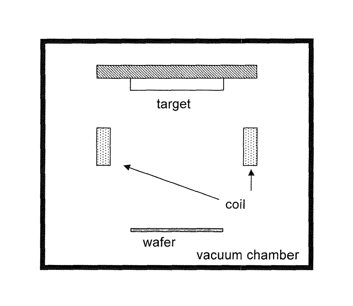
[0099]The sputtering target dehydrogenated by heating was installed in a sputtering apparatus (vacuum chamber) within 1 hour. As a result, the hydrogen gas volume in Example 2 was 100 μL / cm2. The degree of vacuum before sputtering was 1×10⁻⁷ Pa, and the results were good.

example 3

[0100]A target material prepared in the same conditions as those in Example 1 was adjusted the surface roughness by finishing processing, and dehydrogenation thereof was performed in the following conditions:

[0101]Surface roughness of the target: 0.2 μm

[0102]Heating conditions of the target: argon gas atmosphere, a temperature of 700° C., for 2 hours.

[0103]The sputtering target dehydrogenated by heating was installed in a sputtering apparatus (vacuum chamber) within 2 hours. As a result, the hydrogen gas volume in Example 3 was 300 μL / cm2. The degree of vacuum before sputtering was 2×10⁻⁷ Pa, and the results were good.


PUM

PropertyMeasurementUnit
timeaaaaaaaaaa
timeaaaaaaaaaa
timeaaaaaaaaaa

Abstract

Provided is a sputtering target and / or a coil disposed at the periphery of a plasma-generating region for confining plasma. The target and / or the coil has a surface to be eroded having a hydrogen content of 500 μL / cm2 or less. In dealing with reduction in the hydrogen content of the surface of the target and / or the coil, the process of producing the target and / or the coil, in particular, the conditions for heating the surface of the target and / or the coil, which is thought to be cause of hydrogen occlusion, are appropriately regulated. As a result, hydrogen occlusion at the surface of the target can be reduced, and the degree of vacuum during sputtering can be improved. Thus, the present invention provides a target and / or a coil that has a uniform and fine structure, makes plasma stable, and allows a film to be formed with excellent uniformity and provides a method of producing the target and / or the coil.

Description

BACKGROUND[0001]The present invention relates to a sputtering target and / or a coil that can increase the degree of vacuum during sputtering, have uniform and fine structures, give stable plasma, and allow production of a film having excellent uniformity, and relates to a method of producing such a target or a coil.[0002]Recent years, sputtering is used for forming a coating of, for example, a metal or a ceramic material in various fields such as electronics, corrosion-resistant materials, decorations, catalysts, and production of cutting / abrasive materials and wear-resistant materials.[0003]Though sputtering itself is a well-known method, recently, in particular, in the electronics field, sputtering targets suitable for forming coatings with complicated shapes, circuits, barrier films, or other films have been being required.[0004]In general, a target is produced from an ingot or billet prepared by melting / casting a metal, an alloy, or another material through hot forging, annealing...

Claims


Application Information

Patent Timeline
Patent Type & Authority Patents(United States)
IPC IPC(8): C23C14/00C22C14/00C22F1/00C22F1/18C22C27/02H01J37/34C21D1/74C23C14/34C21D3/06
CPCC23C14/34C21D3/06C22C14/00C22C27/02C22F1/00C22F1/18C22F1/183C23C14/3414C23C14/3471H01J37/3426H01J37/3464H01J37/3491H01J37/3497C21D1/74Y10T29/49865
Inventor NAGATA, KENICHIMAKINO, NOBUHITO
Owner JX NIPPON MINING & METALS CORP
Why Eureka
Try Eureka