Fractionating apparatus having colonies of pillars arranged in migration passage at interval and process for fabricating pillars

a technology of pillars and pillars, which is applied in the direction of isotope separation, diaphragms, electrolysis, etc., can solve the problems of large amount of sample required, long time required by researchers for fractionation, and inability to meet researchers' resolution

Inactive Publication Date: 2003-03-13
NEC CORP
View PDF2 Cites 61 Cited by
  • Summary
  • Abstract
  • Description
  • Claims
  • Application Information

AI Technical Summary

Problems solved by technology

However, the researchers require a long time for the fractionation through the ultracentrifugal separator and the capillary electrophoresis system.
Another drawback inherent in those prior art apparatus / system is that a large amount of sample is required.
Moreover, the resolution does not satisfy the researchers.
The object to be fractionated is cells, viruses, macromolecules and minute particles according to the U.S. Patent. However, the prior art apparatus has the following problems.
First, the paths in the obstacle arrays are liable to be clogged with the fragments.
This means that the clogged paths are to be frequently cleaned.
This results in a low throughput.
Second, it is difficult to form the obstacles at fine pitches.
It is impossible to form the obstacles at the fine pitches equal to or less than 200 nanometers through the technologies in those days.

Method used


Image

  • Fractionating apparatus having colonies of pillars arranged in migration passage at interval and process for fabricating pillars
  • Fractionating apparatus having colonies of pillars arranged in migration passage at interval and process for fabricating pillars
  • Fractionating apparatus having colonies of pillars arranged in migration passage at interval and process for fabricating pillars

Examples


first embodiment

[0107] First Embodiment

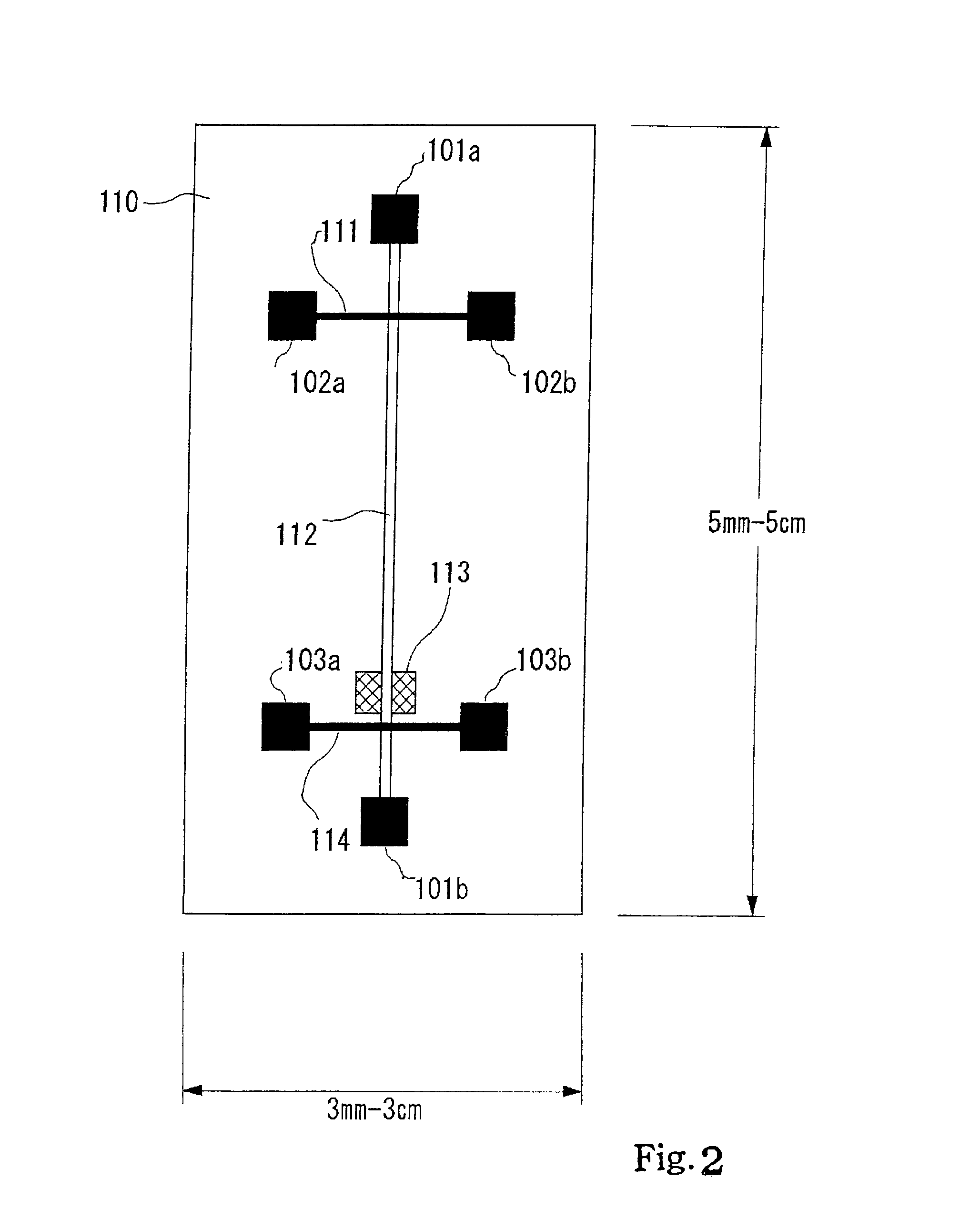
[0108] Referring first to FIG. 2 of the drawings, an apparatus embodying the present invention comprises a substrate 110 and a cover plate 801 (see FIGS. 3 and 4). Although a controller and a sample accelerator are further incorporated in the apparatus, they are not shown in FIG. 2.

[0109] The substrate 110 measures 5 millimeters to 5 centimeters by 3 millimeters to 3 centimeters. A fractionating passage 112 is formed in the substrate 110, and extends in the longitudinal direction. Though not shown in FIG. 1, pillars are formed in the fractionating passage 112. The pillars are designed to trap microstructures, i.e., molecules of a certain size. While a sample is migrated through the fractionating passage 112, the sample is fractionated into fractions different in size. Thus, the fractionating passage 112 partially serves as a fractionating region and partially as a path through which a sample is migrated.

[0110] Liquid sumps 101a and 101b are formed in the subst...

second embodiment

[0119] Second Embodiment

[0120] FIG. 5 shows another apparatus embodying the present invention. The apparatus implementing the second embodiment comprises a sample accelerator 10, a fractionating unit 20 and a controller 21. The fractionating unit 20 includes a substrate 20A and a cover plate 20B (see FIG. 6) as similar to that of the first embodiment. A fractionating passage 20a and a feed passage 19 are formed in the substrate 20A, and the fractionating passage 20a crosses the feed passage 19 at right angles. Pillars are formed in the fractionating passage 20a, and are designed to trap microstructures of a predetermined size thereinto. The pillars occupy an area of the fractionating passage 20a, and the remaining area serves as a path for large-sized microstructures. Openings 20c are formed in the cover plate, and are aligned with both end portions of the fractionating / feed passages 20a / 19. In this instance, the openings have a diameter of the order of 2 millimeters.

[0121] The samp...

third embodiment

[0130] Third Embodiment

[0131] FIG. 7 shows a major surface of a substrate forming a part of yet another apparatus embodying the present invention. In the apparatus implementing the third embodiment, sample is migrated with an assistance of the capillary phenomenon. The apparatus implementing the third embodiment comprises a sample accelerator 530 and a fractionating unit 550. The sample accelerator 530 accelerates sample through the capillary phenomenon.

[0132] The fractionating unit 550 includes a substrate 550a and a cover plate (not shown), and the sample accelerator 530 is built in the substrate 550a as will be described hereinafter in detail. A fractionating passage 540 and a quantitative passage 530a are formed in the substrate 550a, and are open on the major surface of the substrate 550a. Pillars are formed in the fractionating passage 540, and are hereinbelow referred to as "fractionating pillars". The fractionating passage 540 extends in the longitudinal direction of the sub...


PUM

PropertyMeasurementUnit
widthaaaaaaaaaa
widthaaaaaaaaaa
widthaaaaaaaaaa

Abstract

A fractionating apparatus is used for fractionating sample into micro-structures different in size, and includes a fractionating unit formed with a fractionating passage; the fractionating passage is defined in a groove formed in a substrate of the fractionating unit, and pillar patches are formed in the groove at intervals wider than the gap among the pillar patches; while the sample is migrated through the fractionating passage, small-sized DNA molecules are trapped in the pillar patches, and large-sized DNA molecules are smoothly migrated through the wide intervals; this results in that the large-sized DNA molecules reaches the end of the fractionating passage faster than the small-sized DNA molecules without clogging.

Description

[0001] This invention relates to fractionating technologies for a sample containing microstructures and, more particularly, to an apparatus for fractionating a sample into various sorts of microstructures different in size, i.e., cells and fragments of nucleic acid or organic molecules such as amino acids, peptides and proteins, metal ions, colloid and latex beads by using micro-scales and a process for fabricating micro pillars.DESCRIPTION OF THE RELATED ART[0002] In the analysis on basic building bodies of living creatures, it is popular to fractionate microstructures from a sample and refine the microstructures. Another process popular in the analysis is to sort microstructures in a sample into groups different in length or the amount of electric charge. For example, in the Maxam-Guilbert method, DNA (DeoxyriboNucleic Acid) molecules are marked at one ends with radioisotope .sup.32P, and are chemically cut into fragments, which are different in length; thereafter, the fragments a...

Claims


Application Information

Patent Timeline
Patent Type & Authority Applications(United States)
IPC IPC(8): B01L3/00B01L99/00G01N15/10G01N15/14G01N27/447G01N30/02G01N30/28G01N30/60
CPCB01L3/502753B01L3/502761B01L2200/0647B01L2200/0652B01L2400/086G01N27/44704G01N27/44773G01N30/02G01N30/6052G01N2030/285B01D15/34
Inventor IIDA, KAZUHIROKAWAURA, HISAOBABA, MASAKAZUSAKAMOTO, TOSHITSUGUSANO, TORUIGUCHI, NORIYUKI
Owner NEC CORP
Why Eureka
Try Eureka