Coil for electrical and electronic equipment as well as process for production thereof

a technology of electrical and electronic equipment and process, which is applied in the manufacture of coils, basic electric elements, electrical apparatuses, etc., can solve the problems of increased flexural strain, increased manufacture costs, and increased flexural strain

Inactive Publication Date: 2003-03-20
HITACHI CABLE
View PDF4 Cites 41 Cited by
  • Summary
  • Abstract
  • Description
  • Claims
  • Application Information

AI Technical Summary

Problems solved by technology

However, flexural strain increases with increase in width of a conductor or decrease in a diameter of a coil that is defined by a distance along the center line of the coil in the cross section thereof extending from a core of the conductor on either side of the coil to another core thereof on the side opposite to the former (see FIG. 2(a)) (hereinafter referred to simply as "coil core diameter") Due to the fact as described above, there is such a disadvantage that the conductor a is broken at a blast when exceeding a certain limit.
However, troublesome operations are required in these manners, so that there is a problem of increase in manufactures' costs.

Method used


Image

  • Coil for electrical and electronic equipment as well as process for production thereof
  • Coil for electrical and electronic equipment as well as process for production thereof
  • Coil for electrical and electronic equipment as well as process for production thereof

Examples


Embodiment Construction

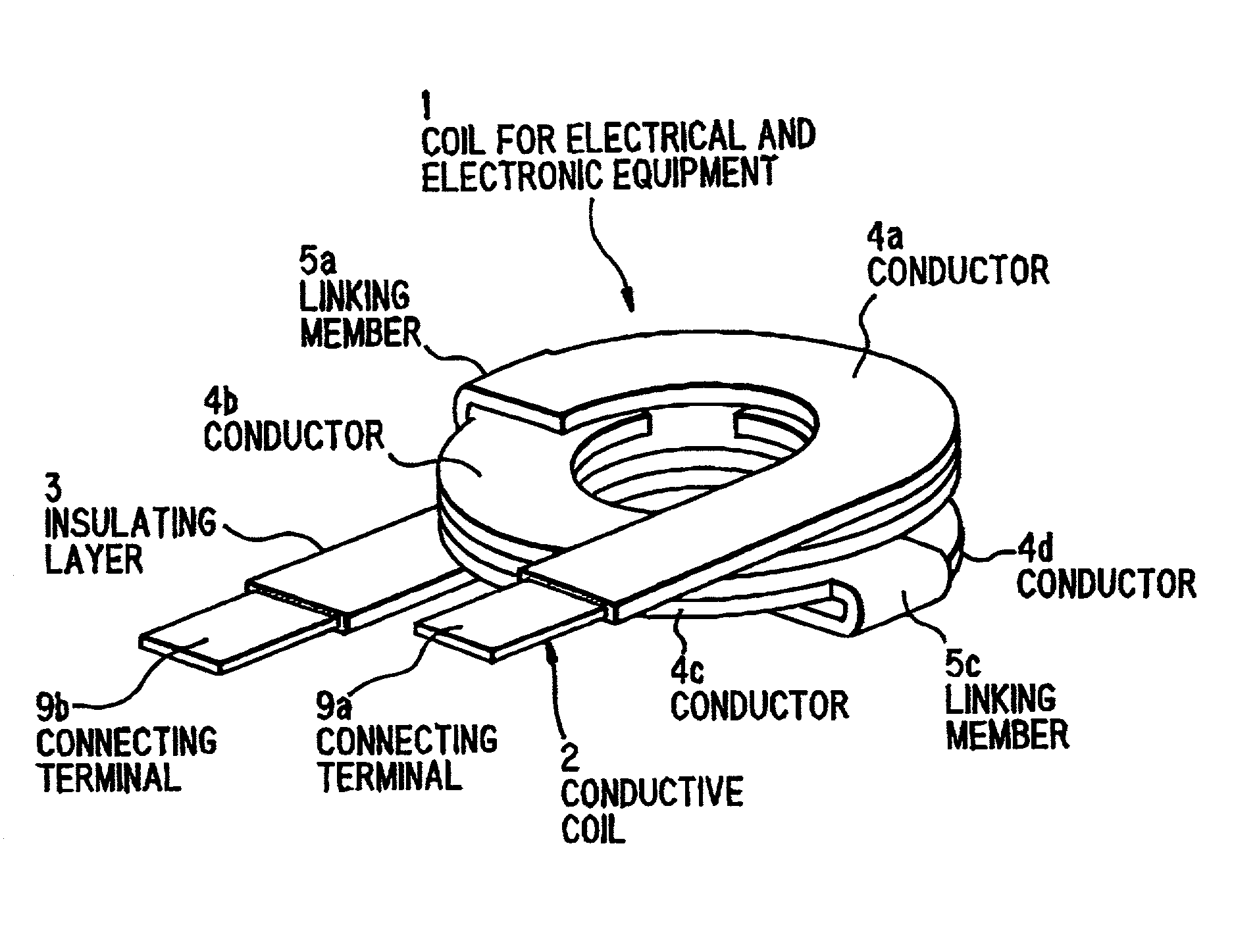
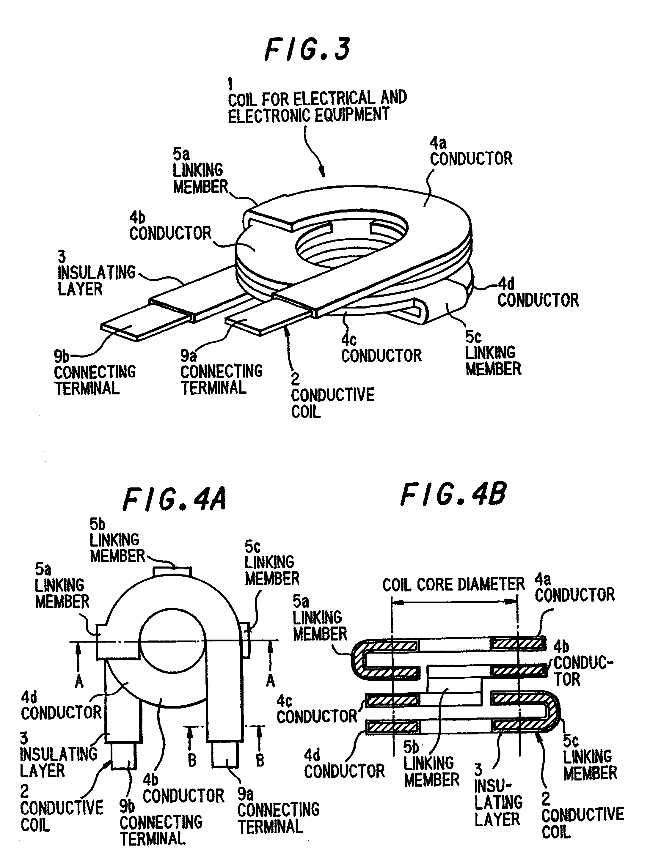
[0041] In accordance with the constitution as described above, a material conductor of OFC (oxygen free high conductivity copper) having 15% breaking extension was used as a conductor plate 8, and a conductor coil 2 having 4 mm conductor width, 0.5 mm thickness, 2.5 turn, and 10 mm coil core diameter was formed. An insulating layer 3 composed of a PI film with an epoxy adhesive (25 .mu.m PI thickness, and 30 .mu.m epoxy adhesive thickness) was applied to the surface of the conductor coil 2 to prepare a coil 1. The resulting coil 1 was subjected to a variety of reliability tests required for usual coils for electrical and electronic equipment such as those of dielectric strength, heat resistance, and flame resistance. As a result, it was proved that various characteristic properties were practically good in the coil 1 according to the present invention without accompanying any trouble. In this connection, when a coil having the same size as that containing a conductor of 15% breaking...


PUM

PropertyMeasurementUnit
diameteraaaaaaaaaa
angleaaaaaaaaaa
angleaaaaaaaaaa

Abstract

A coil for electrical and electronic equipment comprises a spiral conductor coil 2 prepared by disposing coaxially a plurality of conductors 4a through 4d each having a flat circular arc-shaped configuration in multiple stages along a vertical direction, and linking sequentially ends of these conductors 4a through 4d to each other by means of linking members 5a through 5c in the vertical direction; and an insulating layer 3 covering the surface of the conductor coil 2, so that a relationship between a conductor width and a coil core diameter does not depend mutually, it becomes possible to increase and decrease optionally the conductor width and the coil core diameter, and as a result, a wider conductor width and a smaller coil core diameter in the conductor coil 2 than that of a conventional coil can be achieved.

Description

[0001] 1. Field of the Invention[0002] The present invention relates to a coil for electrical and electronic equipment used for inductance, noise or the like filter as well as a process for the production thereof.[0003] 2. Prior Art[0004] Heretofore, a coil produced in accordance with such a manner that a conductor a having a circular or a rectangular section, as shown in FIG. 1 or FIG. 2(b), is worked into a spiral configuration, a surface of the resulting spiralled product is coated with varnish-like polyimide or the like and cured, and then the product thus coated is covered with an insulating material has been principally used as coils for electrical and electronic equipment.[0005] With a recent tendency of high technology in electrical and electronic equipment, a high current-use coil applied to such high-tech electrical and electronic equipment for achieving a short length thereof involves principally a strip-shaped and straight angle conductor a of a section having a wide bre...

Claims


Application Information

Patent Timeline
Patent Type & Authority Applications(United States)
IPC IPC(8): H01F17/02H01F27/28H01F27/32H01F41/04
CPCH01F27/2847H01F27/323H01F41/04
Inventor YAMANOBE, HIROSHIICHIKAWA, TAKAAKIKOMORI, TSUTOMUKOMATSU, HIROAKI
Owner HITACHI CABLE
Why Eureka
Try Eureka