Bushing assembly having a self-alignment function

a self-aligning and assembly technology, applied in the direction of sliding contact bearings, manufacturing tools, rod connections, etc., can solve the problems of easy loosing of inner bushings or outer bushings, affecting the performance of the assembly, and prolonging the required period

a self-aligning and assembly technology, applied in the direction of sliding contact bearings, manufacturing tools, rod connections, etc., can solve the problems of easy loosing of inner bushings or outer bushings, affecting the performance of the assembly, and prolonging the required period

US20030061679A1Inactive Publication Date: 2003-04-03AVISION INC TAIWAN

Image

  • Bushing assembly having a self-alignment function
  • Bushing assembly having a self-alignment function
  • Bushing assembly having a self-alignment function

Examples


Embodiment Construction

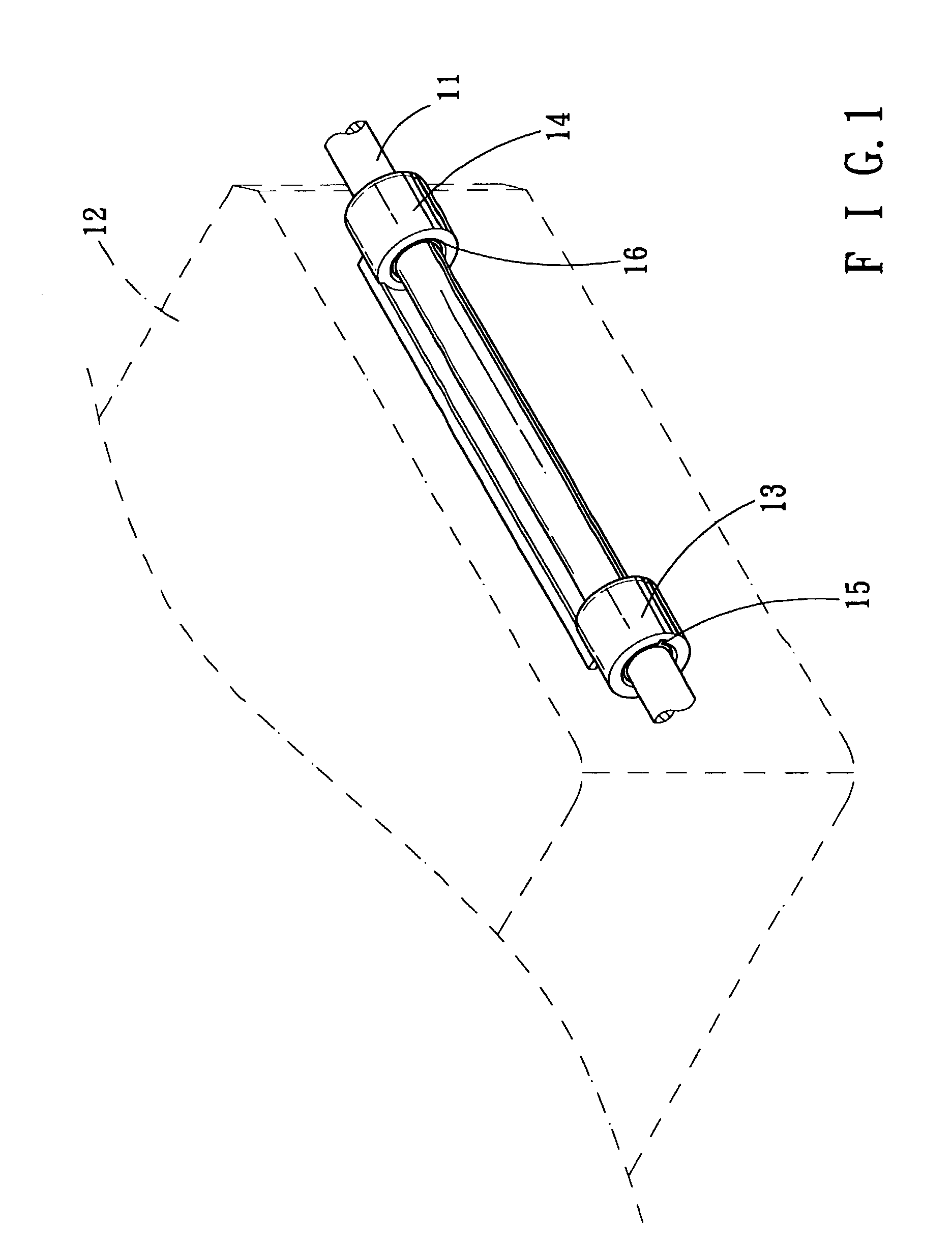
[0035] FIG. 1 shows an assembly of a shaft and a chassis. The chassis 12 has one side provided with two opposite outer bushings 13 and 14, and two inner bushings 15 and 16 mounted in the two opposite outer bushings 13 and 14. The shaft 11 is extended through the two inner bushings 15 and 16 to combine with the chassis 12. The chassis 12 may move in the axial direction of the shaft 11 reciprocally.

[0036] The two outer bushings 13 and 14 have the same structure, and the two inner bushings 15 and 16 also have the same structure. Thus, just only an assembly of one outer bushing 13 and one inner bushing 15 are described as follows.

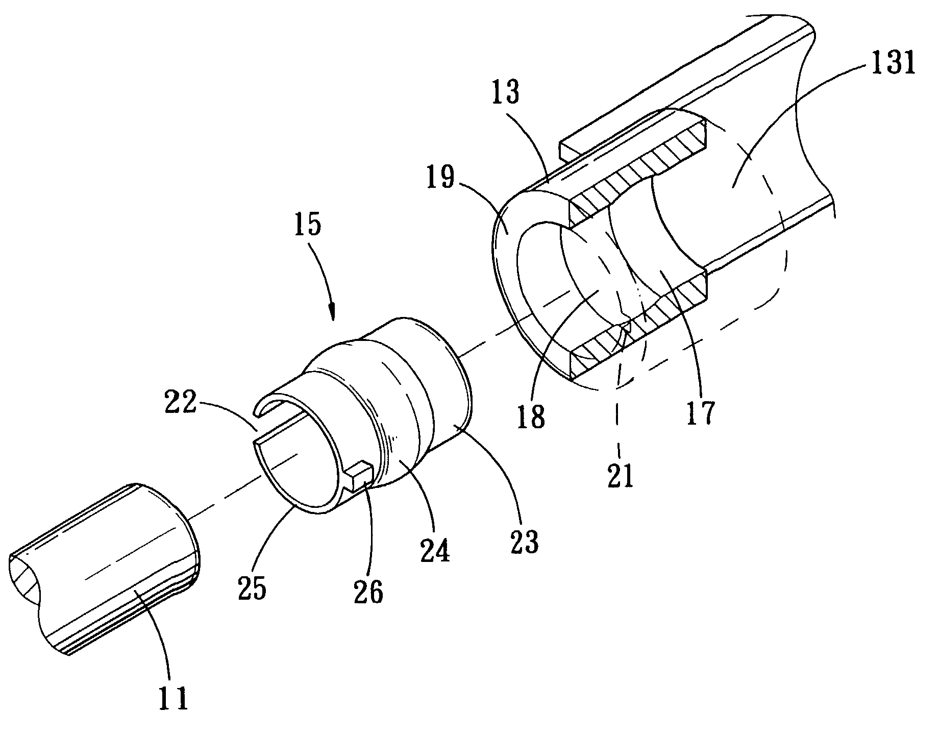
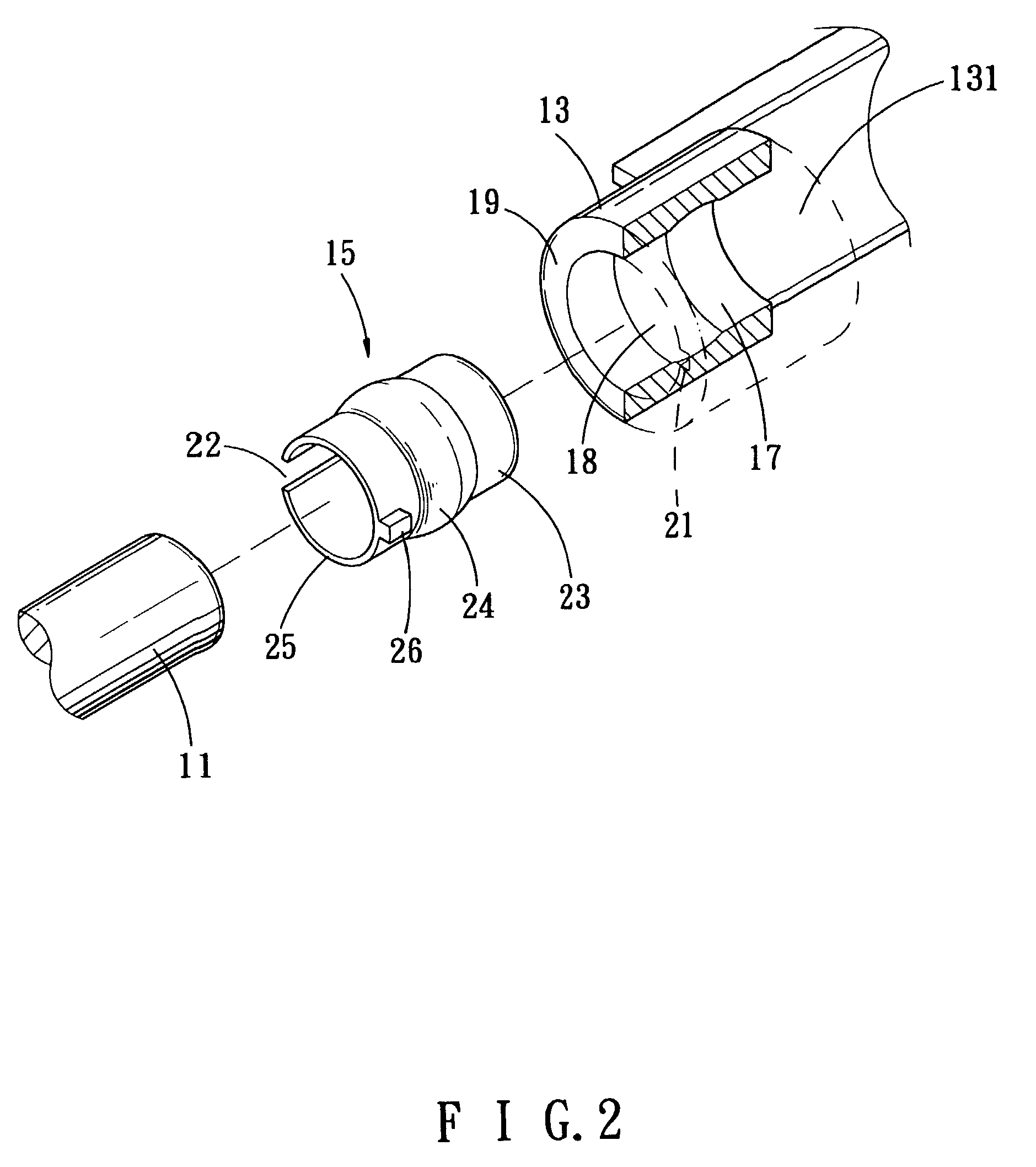
[0037] FIG. 2 shows a combination of an inner bushing and an outer bushing in accordance with one embodiment of the present invention. The outer bushing 13 is axially formed with a shaft hole 131 which has an inner wall face 17 formed with an annular concave arcuate face (annular groove) 18. The inner wall face 17 of the shaft hole 131 of the outer bushing 13 i...


PUM


Abstract

A bushing assembly having a self-alignment function includes inner bushings mounted in outer bushings. A center adjustment unit is mounted between the outer bushing and the inner bushing, and includes convex arcuate faces mating with concave arcuate faces. Thus, the inner bushing may micro-adjust an assembly angle automatically, to maintain at the same axis with other inner bushing, thereby facilitating passage and mounting of a shaft. In addition, the outer bushing or the inner bushing is formed with a slit, or the outer bushing may be made detachable, so that the outer bushing and the inner bushing may be combined easily.

Description

[0001] 1. Field of the Invention[0002] The present invention relates to a bushing assembly having a self-alignment function, which may be mounted on a chassis (optical module) of an image input / output device, so that the inner bushing may be adjusted an assembly angle, and the outer bushing and the inner bushing may be combined easily.[0003] 2. Description of the Related Art[0004] An image capture device, such as a scanner, is provided with a chassis for scanning and receiving images.[0005] At least one side of the chassis is provided with two opposite outer bushings located at the same axis, and an inner bushing is mounted in each outer bushing. A shaft passes through the inner bushings in the outer bushings. Thus, the chassis may combine with the shaft, and the chassis may move along the axial direction of the shaft reciprocally.[0006] Recently, the inner bushing is made by a sintered copper alloy, and contains impregnated lubricating oil. The housing of the chassis is made of pla...

Claims


Application Information

Patent Timeline
03 Apr 2003
Publication
US20030061679A1
IPC
F16B7/04; F16C23/04; F16C29/02; H04N1/04
CPC
F16B7/0406; F16C23/045; Y10T16/05; H04N1/04; H04N2201/0442; F16C29/02
Inventors
CHANG, MARTIN; CHENG, CLARK