Self-leveling constructional laser

Inactive Publication Date: 2003-04-03
HILTI AG
View PDF8 Cites 44 Cited by
  • Summary
  • Abstract
  • Description
  • Claims
  • Application Information

AI Technical Summary

Problems solved by technology

Stands and other auxiliary equipment are no

Method used


Image

  • Self-leveling constructional laser
  • Self-leveling constructional laser

Examples


Embodiment Construction

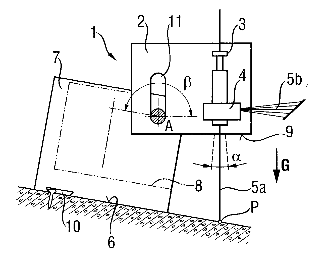
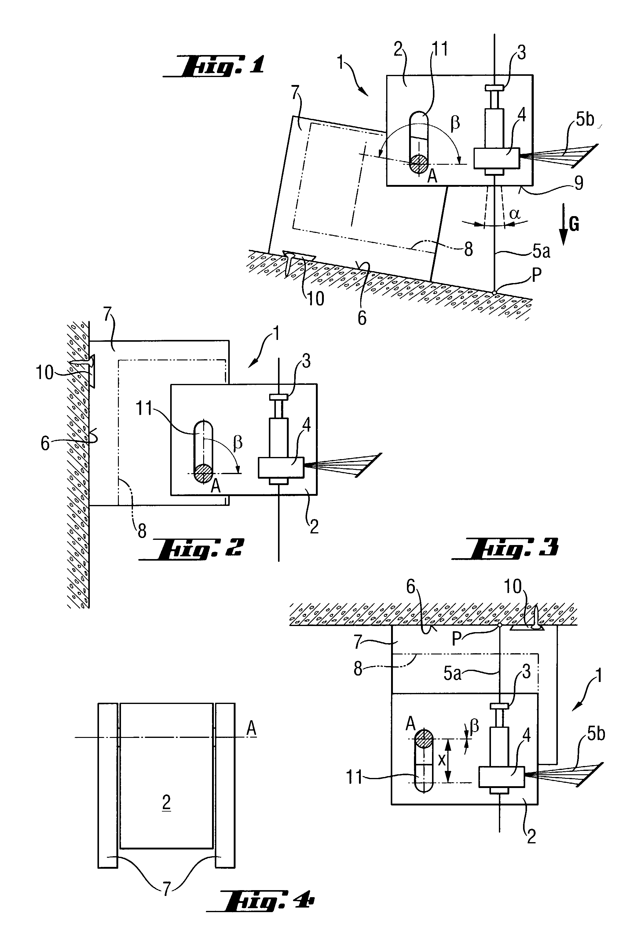
[0027] A self-leveling laser 1, which is shown in FIG. 1, includes a compact housing 2 and an electrooptical system 4 suspended in the housing 2 by a pendulum suspension 3. The electrooptical system 4 self-straightens by the gravity force b within a self leveling region a. The electrooptical system 4 generates two light beams a plumb, punctually focused, visible light beam 5a and a horizontal, linearly focused in a sector, visible light beam 5b. For mounting the laser 1 on a steeply inclined bearing support 6, the laser 1 is provided with a stand 7 fixedly secured to a side of the laser housing 2. The housing 2 pivots about an axle A in an angular region .beta. of about 180.degree. from its transportation position 8, in which the plate-shaped stand 7 covers the housing, to its use position. The housing 2 pivots transverse to the light beams 5a, 5b. The pivot axis A, which is spaced from a side center point of the housing 2, insures that the lower side surface 9 lies free, and the li...


PUM


Abstract

A constructional laser including a self-leveling optical system located in the laser housing (2) and generating a visible plumb light beam (5a) and/or visible horizontal light beam (5b), and a stand (7) fixedly secured to the housing (2) for mounting the housing on a bearing support (6), with the stand (7) being continuously pivotable about a pivot axis (A) transverse to the light beam (5a, 5b) in an angular region (↑) of greater than (20°) and discretely pivotable in angular steps encompassing the self-leveling region (a) and locable in its pivotal position.

Description

[0001] 1. Field of the Invention[0002] The present invention relates to a self-leveling constructional laser for generating an optical plumb or leveling beam.[0003] 2. Description of the Prior Art[0004] Generally, a constructional laser, which is capable of self-leveling, under action of a gravity force, in a limited self-leveling region of about .+-.5.degree., includes a housing, and a rotably and substantially fictionlessly securable in the housing, self-leveling electrooptical system for generating a vertical and / or horizontal, punctual and / or linear visible laser beam.[0005] In distinction from the precision measuring technology, in the ragged environment of the construction industry, accessory-free, one-piece constructional lasers with compact housings and, if necessary, shock-absorbing, are used. An often need to use a constructional laser on steeply inclined supports and directly on walls and ceilings usually leads to the use of temporary auxiliary constructions to provide sl...

Claims


Application Information

Patent Timeline
IPC IPC(8): G01C15/00G01C15/10
CPCG01C15/004Y10S33/21G01C15/105
Inventor WAIBEL, REINHARD
Owner HILTI AG
Why Eureka
Try Eureka