Hydraulic drive split lawn roller

Inactive Publication Date: 2003-04-10
WYNINGS ROSS
View PDF0 Cites 16 Cited by
  • Summary
  • Abstract
  • Description
  • Claims
  • Application Information

AI Technical Summary

Benefits of technology

0005] Accordingly, it is an object of the invention to provide an effective and efficient technique for ro

Problems solved by technology

Both of these techniques are slow and awkward, and are somewhat unworkable if the terrain is anything but flat.
Some lawn and construction equipment now exists for rolling earth or topsoil, but these are not entirely suited for the purposes served by this invention.
There is no means

Method used


Image

  • Hydraulic drive split lawn roller
  • Hydraulic drive split lawn roller
  • Hydraulic drive split lawn roller

Examples


Embodiment Construction

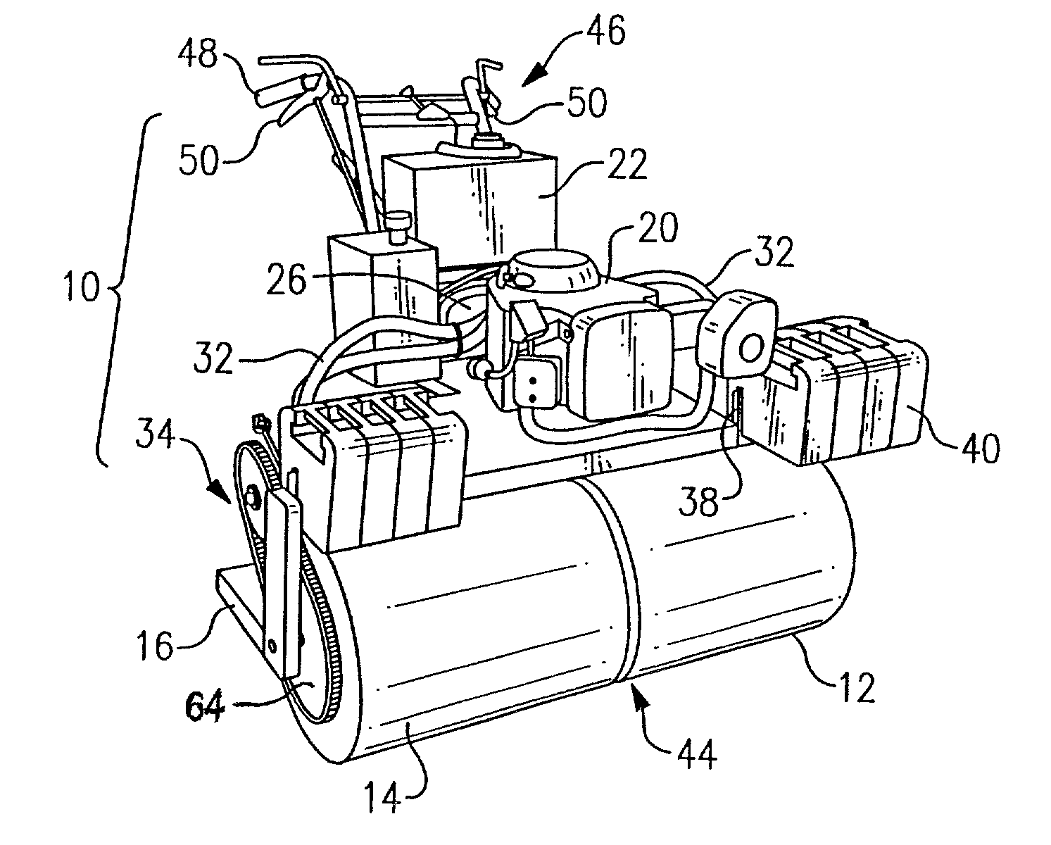
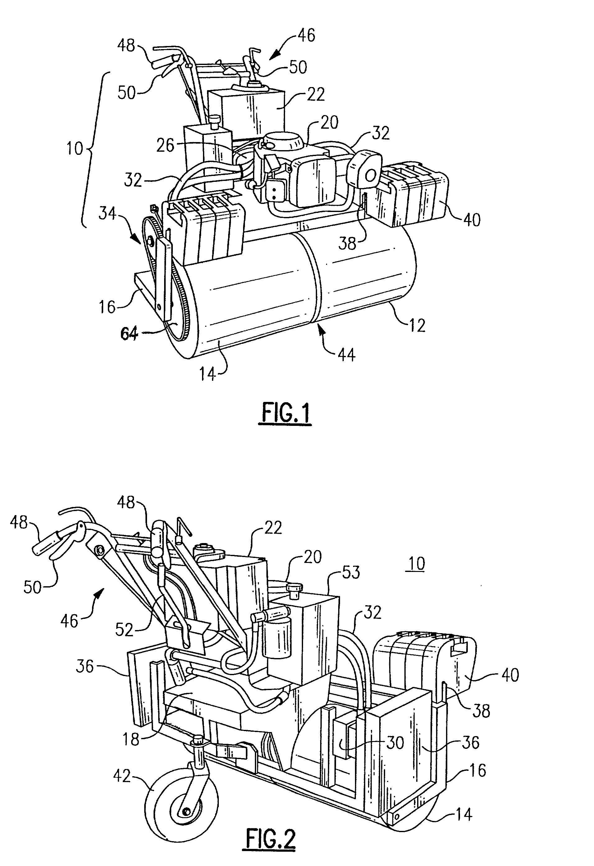
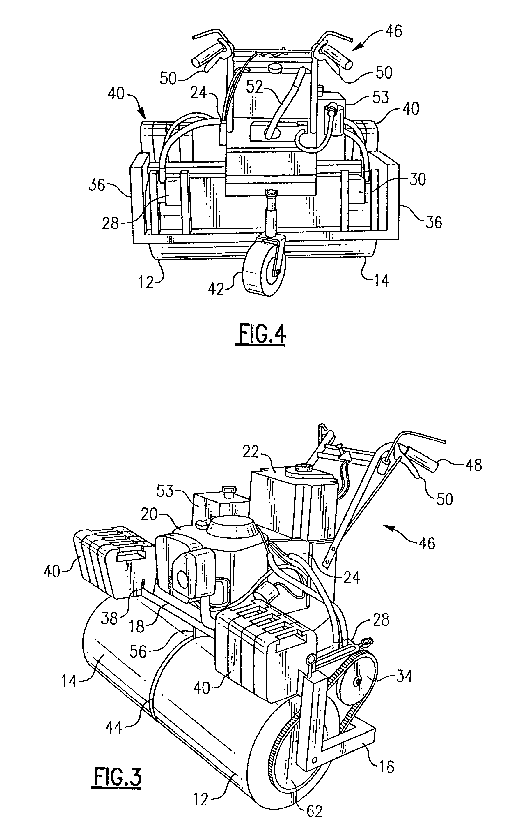
[0019] With reference to the Drawing, and initially to FIGS. 1 to 4 thereof, one preferred embodiment of the split drum lawn roller 10 has a left roller drum 12 and a right roller drum 14, both situated on the same axis. A frame 16 has a central platform 18 on which a gasoline engine 20 is supported, with a fuel tank 22 situated above the engine 20. There are left and right hydraulic pumps 24 and 26 on the platform 18 and connected to the output shaft of the engine 20, and there are left and right hydraulic motors 28, 30 on the frame near the outboard ends of the drums, and these are connected by hydraulic hoses 32, 32 to the respective pumps 24, 26. At each end of the frame there is a chain drive 34, 34 for transferring rotary motion from the respective hydraulic motor to the associated roller drum 12, 14. While a chain drive is shown here, other continuous web drives may be employed, such as a toothed belt drive. Safety covers 36, shown on each side of the frame 16 in FIGS. 2 and ...


PUM


Abstract

A power lawn roller has a left roller drum and a right roller drum, both journalled side by side on the same axle and rotatable independently of one another. Left and right hydraulic drives provide motive power to the left and right roller drums, and each is capable of rotating the associated drum forward, reverse, or at intermediate speeds. Removable external weights are rack mounted on the frame of the unit. The operator can easily control the direction and speed, and the unit is capable of a zero-radius turn.

Description

[0001] This invention relates to lawn and landscaping equipment, and is more particularly directed to self-powered equipment for rolling or compacting soil. The invention is specifically directed to a walk-behind lawn roller that permits an operator to control the direction and speed of travel with great precision, and without risk of damage to existing lawn, pavement or soil.[0002] There now exists a need for a convenient method for rolling down topsoil in preparation for laying down of a new lawn. A need exists for rolling flat existing lawns, as well. At the present time what exists for this purpose is a lawn roller that has to be pulled or dragged by hand, or a roller that has to be towed behind a tractor. Both of these techniques are slow and awkward, and are somewhat unworkable if the terrain is anything but flat. What is needed is a lawn roller that is easy to turn and move about on a yard or lawn, without having to be pushed, pulled, or towed. In order to work the soil in ar...

Claims


Application Information

Patent Timeline
IPC IPC(8): E01C19/26
CPCE01C19/262
Inventor WYNINGS, ROSS
Owner WYNINGS ROSS
Why Eureka
Try Eureka