Bandwidth allocation in a synchronous transmission network for packet oriented signals

a synchronous transmission network and packet oriented technology, applied in the field of packet oriented signal bandwidth allocation in the synchronous transmission network, can solve the problems of inefficient use of synchronous network bandwidth, inability to fit neatly into any synchronous network payload container, and inability to communicate between connected nodes in time, so as to achieve the effect of obviating and/or mitigating

Inactive Publication Date: 2003-04-17
CIENA
View PDF13 Cites 114 Cited by
  • Summary
  • Abstract
  • Description
  • Claims
  • Application Information

AI Technical Summary

Benefits of technology

0022] The invention seeks to mitigate and / or obviate the above mentioned problems associated With the prior art by providing a method of allocating a variable amount of bandwidth in a synchronous transmission network so that scaleable bandwidth is provided without having to perform complex protocol specific functions.

Problems solved by technology

These protocols come in a variety of bandwidths (e.g. Fibre Channel supports 500 Mbits / s, 1 Gbits / s, 2 Gbits / s), many of which do not fit neatly into any synchronous network payload containers.
Geographically dispersed Fibre Channel / ESCON sits can interconnect using other transport mechanisms such as synchronous networks, however several problems are known in the art to be associated with conventional techniques.
Firstly, over long distances, the length of time taken by a receiver ready signal (or any other signal used to implement buffer-to-buffer flow control) to be communicated between connected nodes can be substantial.
This results in an inefficient use of the synchronous network bandwidth which has been allocated for the transmission.
However, the technique has several disadvantages.
Secondly it is unlikely the client signal will operate continuously at its full bandwidth rate.
Such conventional techniques are complex, as protocol dependent functions to manage flow control must be provided in order to prevent loss of data.
Contiguous concatenation techniques have several disadvantages compared to virtual concatenation.
Modifying existing intermediate nodes and / or providing new intermediate network nodes to have the capacity to cope with contiguous concatenated containers is both costly and time consuming.
Although contiguous and particularly virtual concatenation provide many different payload sizes in which to transport client signals, in reality very few payload rates are supported for most protocols.
There are several reasons for this including, the lack of granularity of contiguous concatenation, the relatively recent introduction of virtual concatenation, the complexity involved in implementing virtual concatenation, and the complexity of protocol specific functions required to support payloads less than the full bandwidth of the client signals.
There is no single known mapping technique for packet oriented client signals employing buffer-to-buffer flow controls which supports a range of virtually concatenated synchronous network payloads.
This technique is limited to contiguous concatenation (STS1, STS3c, STS12c, VC4, VC4-4c), and requires many complex Fibre Channel and ATM functions.
This technique similarly is limited to contiguous concatenation and requires complex protocol functions to achieve the mapping.
No complex protocol specific processing is required as implementation is limited to a single synchronous payload (VC4-6v for SDH, STS3c-6v for SONET) The technique cannot therefore be scaled to meet specific customer bandwidth and cost requirements, and is accordingly inflexible.
Another disadvantage of the third method is that the buffer-to-buffer flow control mechanism escalates the problem of bandwidth wastage in that as data throughput decreases with distance, more bandwidth is wasted.
Yet another disadvantage of the third method is that this size of bandwidth will have limited connection options in the network.

Method used


Image

  • Bandwidth allocation in a synchronous transmission network for packet oriented signals
  • Bandwidth allocation in a synchronous transmission network for packet oriented signals
  • Bandwidth allocation in a synchronous transmission network for packet oriented signals

Examples


Embodiment Construction

[0115] Overview of Fibre Channel

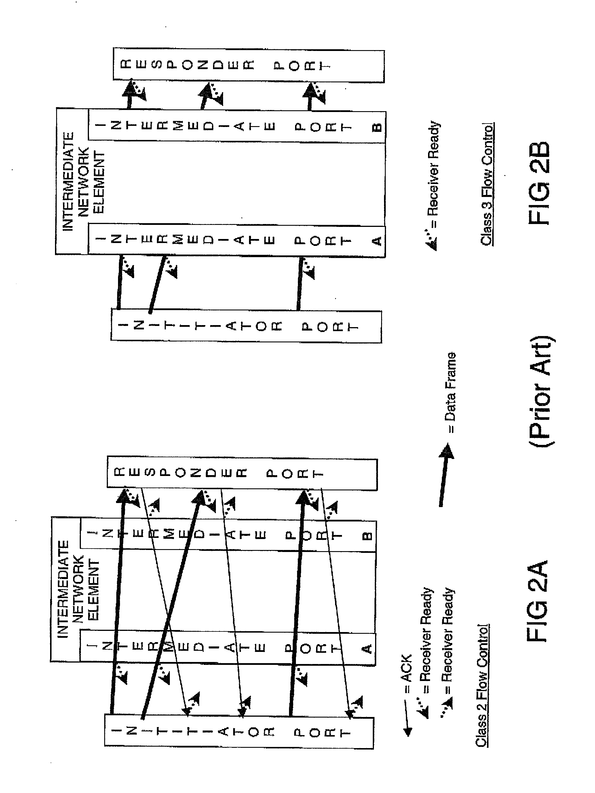
[0116] A detailed overview of Fibre Channel is now given with reference to the accompanying drawings to illustrate a conventional buffer-to-buffer flow control mechanism which Fibre Channel and other upper layer protocols supported by Fibre Channel employ.

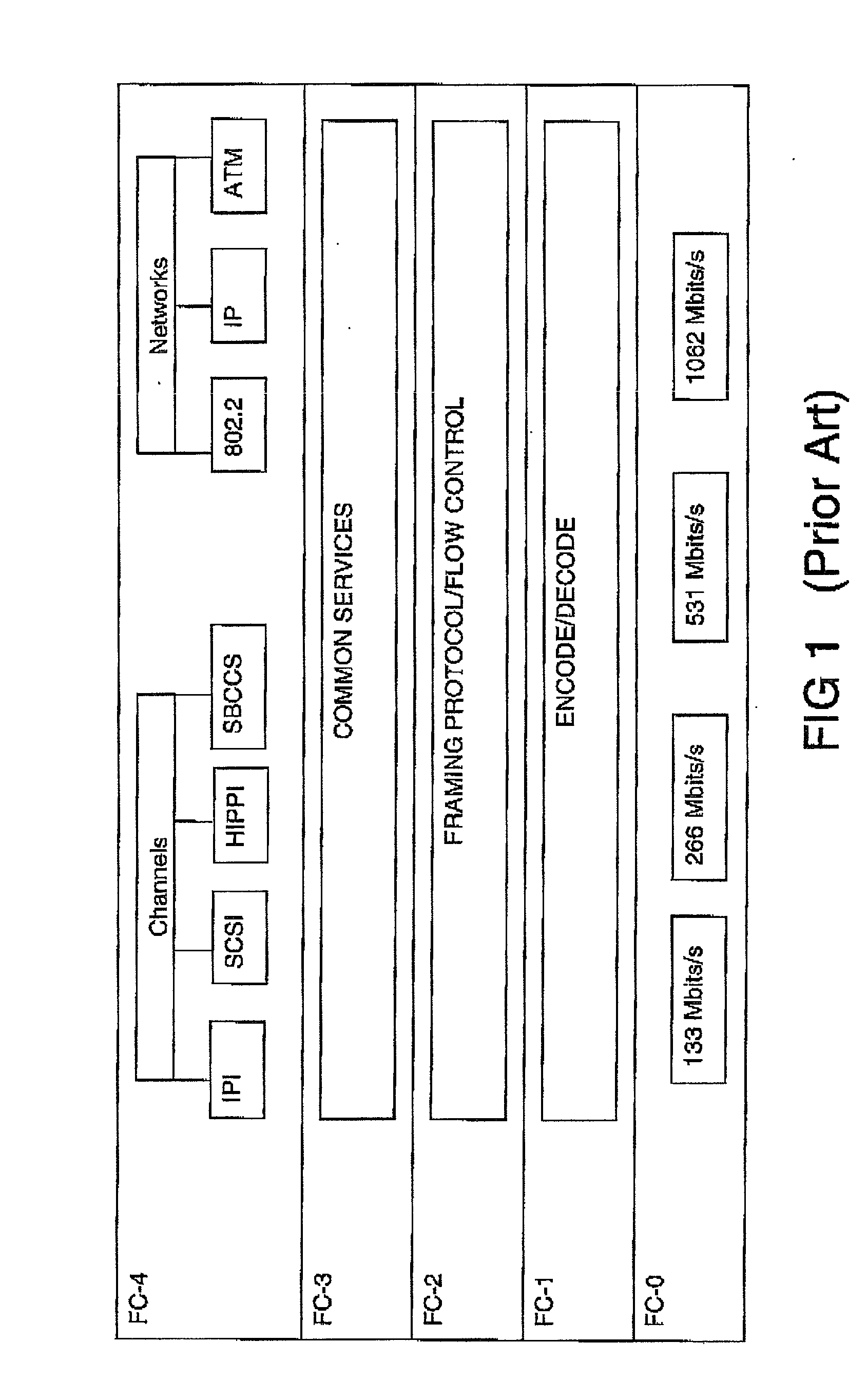
[0117] Firstly, Fibre Channel is a serial link supporting its own protocol as well as upper layer protocols such as FICON, FDDI, SCSI, HIPPI, IPI, IP.etc.

[0118] Protocols traditionally thought of as either channel or network may co-exist on a single Fibre channel physical layer. The lower Fibre channel transport layers are not aware of any "ULP" (Upper Layer Protocol) as is known to those skilled in the art.

[0119] Conventionally, Fibre Channel enables large amounts of information to be transferred rapidly. Transmission speeds include 133 Mbits / s, 266 Mbit / s, 530 Mbit / s, 1.0625 and 2.1250 Gbit / s (higher transmission speeds may be provided in future based on Fibre Channel principles). Fibre Channel is ...


PUM


Abstract

A method of transporting a packet oriented client signal which uses a buffer-to-buffer flow control mechanism over a synchronous transmission network by assigning an arbitrary synchronous payload, where the synchronous payload bandwidth may be significantly smaller than the full bandwidth of the client signal. Flow control over the synchronous network is provided by the buffer-to-buffer flow control mechanism of the client signal to automatically regulate the data throughput to ensure no data can be lost. The method is independent of the Client Signal Data Rate and the provisioned SDH/SONET bandwidth, and SDH/SONET payload which may be non-concatenated, contiguously concatenated, or virtually concatenated. In particular, the method may be used to support the transport of Fibre Channel (1G, 2G and 4G), and ESCON (200M) in a synchronous payload.

Description

[0001] The present invention relates to a method of mapping a packet orientated client signal to a synchronous network payload. In particular, but not exclusively to a method of allocating bandwidth in a synchronous digital network for a packet oriented signal having buffer-to-buffer flow control, and to related aspects thereof.[0002] In this document, the use of the term a synchronous network infers a reference to a SONET (Synchronous Optical NETwork) and / or a SDH (Synchronous Digital Hierarchy) network. The use of either the term SDH or SONET does not exclude a reference to the other such as a person skilled in the art would appreciate.[0003] Such synchronous networks support a hierarchical multiplexing structure of synchronous network signals. Thus the payloads of synchronous network signal frames are able to transport lower-speed signals within containers, and smaller containers can be encapsulated within larger containers.[0004] Two types of client signal are normally carried w...

Claims


Application Information

Patent Timeline
Patent Type & Authority Applications(United States)
IPC IPC(8): H04J3/16H04Q11/04
CPCH04J3/1617H04J2203/0069H04Q11/0478H04J2203/0098H04J2203/0071
Inventor SMITH, RORYHENDRON, JAQUELINEREA, IVOR
Owner CIENA
Why Eureka
Try Eureka