Vehicle engine control

a technology for engine control and vehicles, applied in the direction of electric control, speed sensing governors, machines/engines, etc., can solve the problems of engine overload, constant varying load demand on the engine and engine drive train, and substantial decrease in engine speed before the engine control uni

Inactive Publication Date: 2003-04-24
DEERE & CO
View PDF0 Cites 31 Cited by
  • Summary
  • Abstract
  • Description
  • Claims
  • Application Information

AI Technical Summary

Benefits of technology

0016] In this invention, an engine control unit uses a power curve or an algorithm for a power curve to pro-actively adjust fuel flow rate to an internal combustion engine, thereby to adjust engine power, in anticipation of changes in loads bein

Problems solved by technology

While the ECU thus responds reactively, step changes in engine loading can cause substantial decreases in engine speed before the engine control unit can respond to the dynamically changing situation.
However, the wide range of operating systems which consume power in the combine results in a constantly varying load demand being placed on the engine and engine drive train.
To the extent multiple load demands increase simultaneously, to the extent a load demand increases step-wise by a substantial amou

Method used


Image

  • Vehicle engine control
  • Vehicle engine control
  • Vehicle engine control

Examples


Embodiment Construction

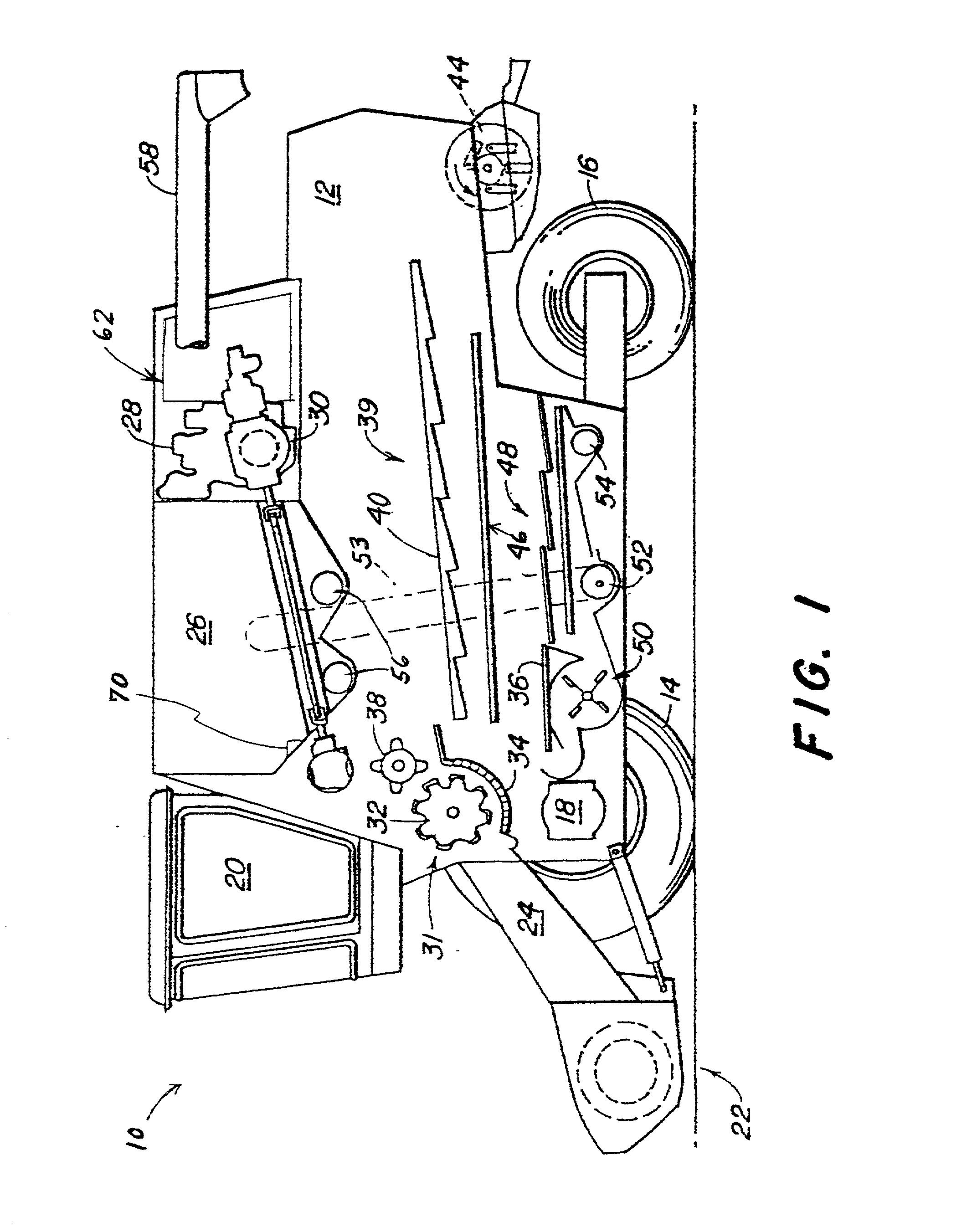
[0044] FIG. 1 illustrates an agricultural combine 10 having a chassis 12 and ground engaging wheels 14 and 16. Forward ground engaging wheels 14 are driven by hydrostatic motor 18 located between the wheels. An operator seated in operator control cab 20 controls the operation of the combine. Harvesting platform 22 extends forward from the chassis and is used for severing the crop material from plants in the field which produce such crop material, and for ingesting the so-severed crop material into the combine. After the crop material is ingested into the combine, the crop material is directed through feeder house 24 and into those portions of the combine which separate the crop material from unwanted portions of crop residue such as plant material other than the crop material, and weeds.

[0045] While the invention is described herein in terms of harvesting grain, it should be understood that the invention can apply equally well to implementations employing other vehicles or wherein c...


PUM


Abstract

An engine control unit, and method of use, uses a power curve or algorithm to pro-actively adjust fuel flow rate to an engine, optionally in combination with a reactive power curve or algorithm, thereby to adjust engine power, in anticipation of changes in loads being imposed on the engine, as well as to respond to engine speed changes. The ECU has a power curve or algorithm stored in memory which responds to certain predetermined operating conditions other than sensed engine speed, by providing a sequence of pro-active change inputs, at predetermined rates of change, in rate of delivery of fuel to the engine combustion chambers, independent of engine speed change, thereby to produce pro-active incremental changes in power output of the engine. Such pro-active incremental power changes are effected in anticipation of changes in load demand on the engine, and correspond generally with expected incrementally progressive changes in load demand on the engine. In preferred embodiments, the power curve or algorithm includes a first upwardly sloping line representing small increment increases in engine power, a second step change increase in engine power, a third downwardly sloping line representing small incremental decreases in engine power, and a fourth relatively greater magnitude step change decrease in engine power. The pro-active change input signals can be combined with reactive change input signals to make respective combination change input signals which take into consideration a variety of operating parameters, including engine speed changes.

Description

[0001] This invention is directed to combines and other off-road vehicles powered by internal combustion engines, wherein one or more auxiliary power demands are periodically placed on the engine. The invention is further directed to such vehicles wherein the engine is controlled by an electronic engine control unit as part of an electronic engine control system.[0002] Combines are large agricultural machines used to harvest grain or other crop material from supporting plants. Such harvesting of the crop material includes e.g. cutting plants containing such crop material or otherwise severing the crop material from the plant, threshing and separating the crop material from the plant material, and cleaning the crop material. from the supporting plant material and other debris with which the crop material may be associated. Such combine typically has a grain tank for temporarily storing harvested crop material. The combine also has an unloading auger for unloading the crop material fr...

Claims


Application Information

Patent Timeline
IPC IPC(8): F02D31/00F02D41/08
CPCB60W2300/158F02D41/083F02D31/007
Inventor SHEIDLER, ALAN DAVIDTINGLE, KYLE JOHNHENNINGS, KENNY L.BROCKMANN, WILLIAM A.SAHLIN, MARK PETER
Owner DEERE & CO
Why Eureka
Try Eureka