Eureka AIR delivers breakthrough ideas for toughest innovation challenges, trusted by R&D personnel around the world.

Motorized cart with hub gear motor system

a technology of motorized carts and gear motors, which is applied in the direction of electric propulsion mounting, folding cycles, cycles, etc., can solve the problems of rear wheel drive, difficult to maneuver carts in an area with limited space,

Inactive Publication Date: 2003-05-08
ASSEMBLED PROD
View PDF18 Cites 24 Cited by
  • Summary
  • Abstract
  • Description
  • Claims
  • Application Information

AI Technical Summary

Benefits of technology

[0009] It is an object of the present invention to provide a motorized cart with a hub gear motor system that is easily maneuverable by an operator.
[0010] It is a further object of the present invention to provide a motorized cart that corners smoothly.
[0011] It is a further object of the present invention to provide a motor arrangement on a three-wheeled motorized cart that inhibits skipping of the front wheel when turning the cart.
[0015] It is a further object of the present invention to provide a motorized cart with an inexpensive and simplified drive means.
[0020] It is a further object of the present invention to provide a motorized cart that has a reduced turning radius.

Problems solved by technology

Because of their size and large turning radius, these carts can be difficult to maneuver in an area with limited space.
Due to such space limitations, most stores and homes are generally unable to accommodate such motorized carts without renovating or rearranging the area in which the carts are to be used.
In addition, having rear wheel drive can reduce the efficiency of the cart's motor since power is lost through the drive train as rotation is transmitted from the motor to the wheel(s) of the cart.
Inherent drawbacks exist with 24-volt battery systems.
Not only is such a system more complex since the batteries are connected in a series, but batteries connected in a series are also difficult to consistently recharge.
Typically, one of the batteries in a series will overcharge and the other battery will fail to fully charge.
Such a recharging routine is inefficient and can be frustrating for a user.
This can significantly increase the weight of the cart and increase the cost of manufacturing.
As a result, carts having rear wheel drive are difficult and cumbersome to operate.
Another drawback to a cart with rear wheel drive is that the front wheel(s) is subject to skipping or skidding across the floor's surface when cornering the cart.
In these instances, the forward movement of the cart overcomes the turning motion of the front wheel and the front wheel is unable to rotate properly to guide the cart, resulting in the wheel skidding or skipping across the surface of the floor.

Method used


Image

  • Motorized cart with hub gear motor system
  • Motorized cart with hub gear motor system
  • Motorized cart with hub gear motor system

Examples


Embodiment Construction

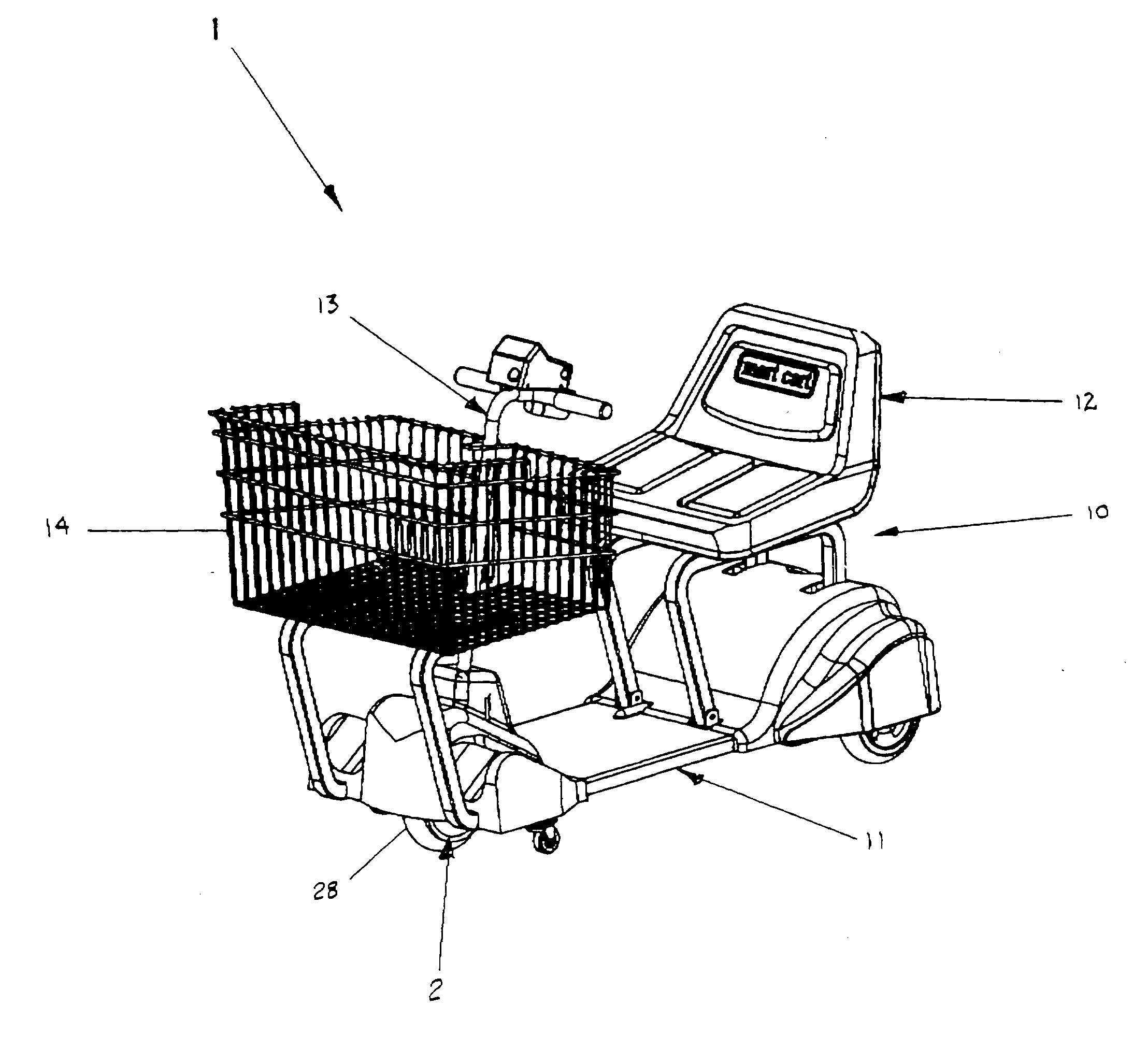
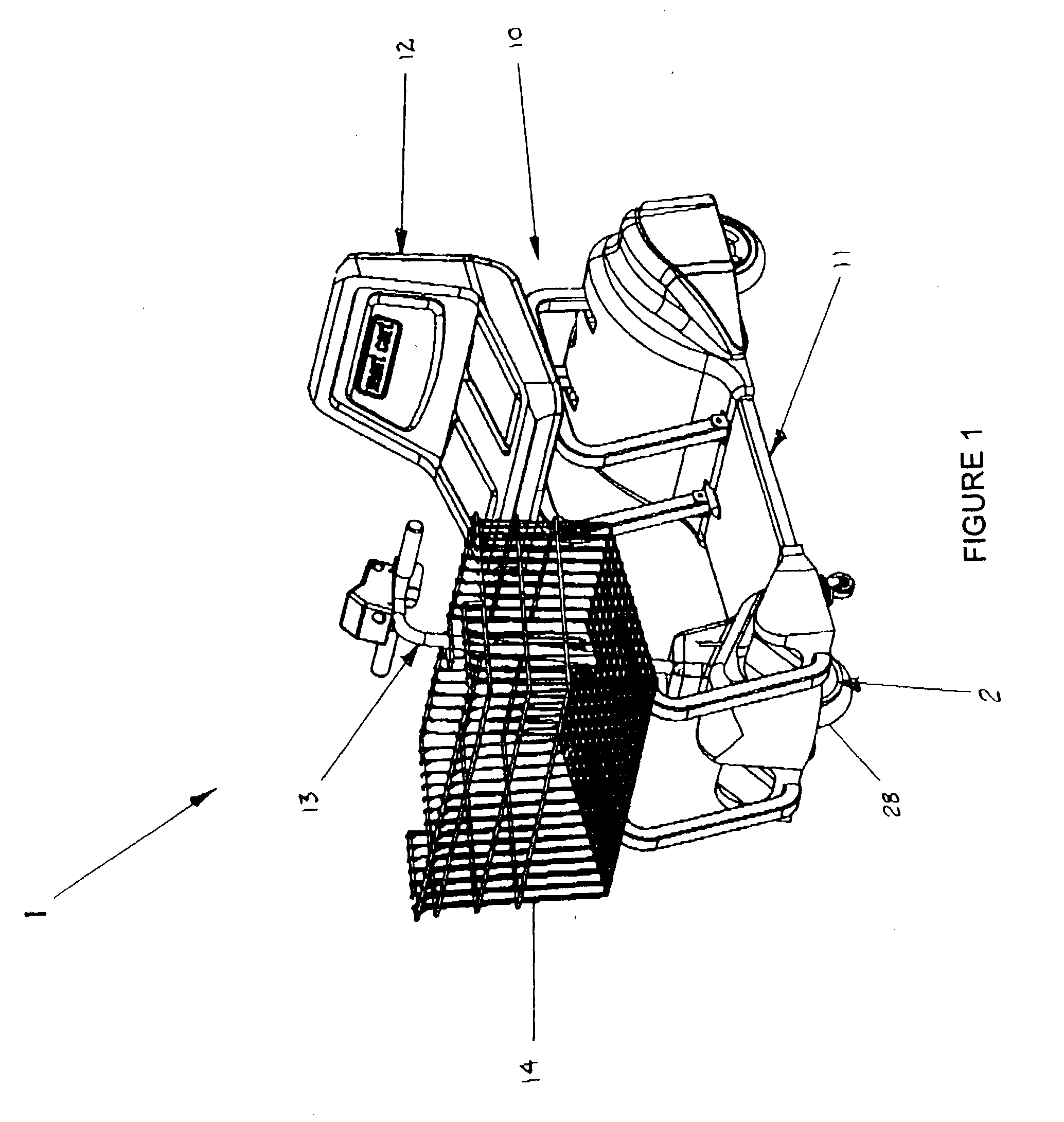
[0032] Referring to the drawings in which like reference numerals designate like or corresponding parts throughout the several views, there is shown in FIGS. 1 and 7, a motorized cart (1) with a hub gear motor system (2). The motorized cart (1) comprises a cart body (10). The hub gear motor system (2) includes means for driving the cart body, means for powering the driving means and means for controlling the driving means.

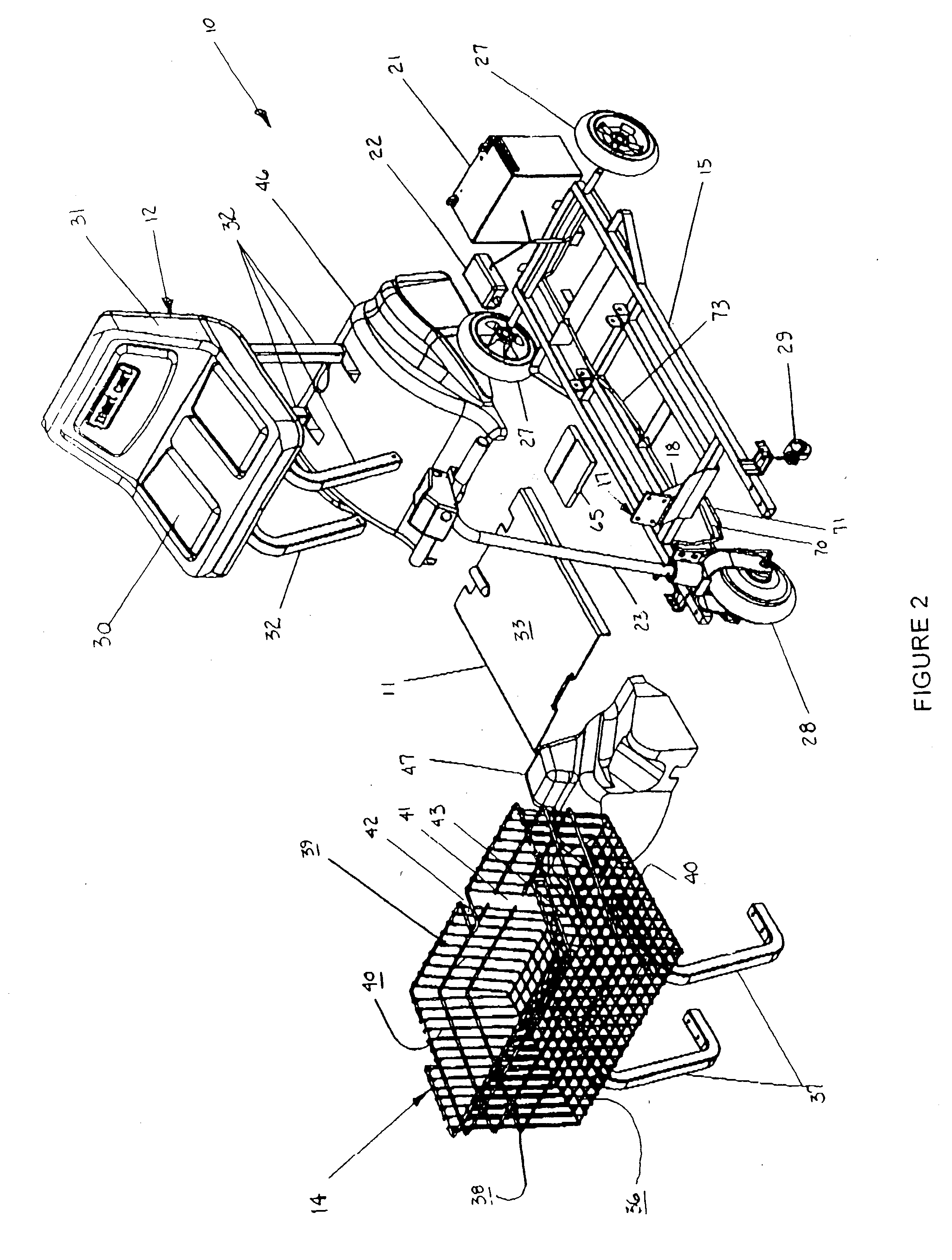
[0033] The cart body (10) includes a platform (11) with a seat (12), a plurality of wheels, a steering unit (13) and a storage receptacle (14). As shown in FIG. 2, the cart body (10) also has a support frame (15) that provides an infrastructure for supporting the seat (12) and the platform (11). The support frame (15) itself is comprised of a plurality of longitudinal pieces and cross pieces. The support frame (15) also includes a column support bracket (17) which has an outer support surface (18) thereon.

[0034] Referring to FIGS. 2 and 3, the steering unit (13) is...


PUM


Abstract

The invention is directed to a motorized cart and a hub gear motor system in which the electric motor of the system is contained within the hub casing of a front wheel of the motorized cart. The hub gear motor system provides the motorized cart with front wheel drive.

Description

I. BACKGROUND[0001] The present invention is directed to a motorized cart with a hub gear motor system. The motorized cart has a front wheel and two rear wheels. The front wheel of the motorized cart is driven by the hub gear motor system which comprises an electric reversible motor that is contained within the front wheel.[0002] Motorized carts are commonly used in stores and homes to provide mobility for individuals that are unable to walk or stand for any length of time. Because of their size and large turning radius, these carts can be difficult to maneuver in an area with limited space. Due to such space limitations, most stores and homes are generally unable to accommodate such motorized carts without renovating or rearranging the area in which the carts are to be used.[0003] Most motorized carts for shopping and home use are powered by electric motors mounted on the frame of the cart. A drive train translates the rotational movement of the motor to one or both rear wheels. Th...

Claims


Application Information

Patent Timeline
IPC IPC(8): B60K1/00B62B3/14B62B5/00B62DB62D1/00B62K5/04
CPCB60K1/04B60K7/0007B60K17/043B60K17/046B60K2001/0416B62K2015/005B60K2007/0092B62B3/14B62B5/0026B62B5/004B62K5/025B60K2007/0038
Inventor TURNER, PATRICK E.
Owner ASSEMBLED PROD
Why Eureka
Eureka Blog
Learn More