Kneading apparatus and method for kneading rubber or rubber composition

a technology of kneading apparatus and kneading method, which is applied in the direction of clay mixing apparatus, mixing/kneading with horizontally mounted tools, transportation and packaging, etc. it can solve the problems of inability to achieve power saving, easy to be complicated and increased in size, and inability to easily control the viscosity level and dispersion level

Inactive Publication Date: 2003-05-15
KOBE STEEL LTD
View PDF14 Cites 11 Cited by
  • Summary
  • Abstract
  • Description
  • Claims
  • Application Information

AI Technical Summary

Problems solved by technology

However, in kneading by using such a s batch-system kneading apparatus, the kneaded product must be transferred to an extruder from the kneading apparatus by using a transport device after the kneading step, and must be molded in a desired shape, thereby causing the need for a step of transferring a bulk kneaded material.
Therefore, the apparatus is easily complicated and increased in size, and a manual work by a worker is required, failing to achieve power saving.
Therefore, the bulk kneaded material after kneading is formed in a sheet and cooled, and again subjected to a re-milling step several times. The re-milling step is repeated until the viscosity is decreased to a desired level, and in some cases, the re-milling step is performed about 5 times. This is undesirable from the viewpoint of improvement in productivity.
The viscosity level and the dispersion level cannot be easily controlled in such a wide range as controlled by a batch-system kneading apparatus.
However, the screw of the double-screw kneading extruder comprises a segmented kneading blade (a rotor segment, kneading disk, a screw segment, or the like), which is combined with a splined shaft, and thus in a large-size equipment, much labor and time are required for changing the shape or configuration the screw.

Method used


Image

  • Kneading apparatus and method for kneading rubber or rubber composition
  • Kneading apparatus and method for kneading rubber or rubber composition
  • Kneading apparatus and method for kneading rubber or rubber composition

Examples


Embodiment Construction

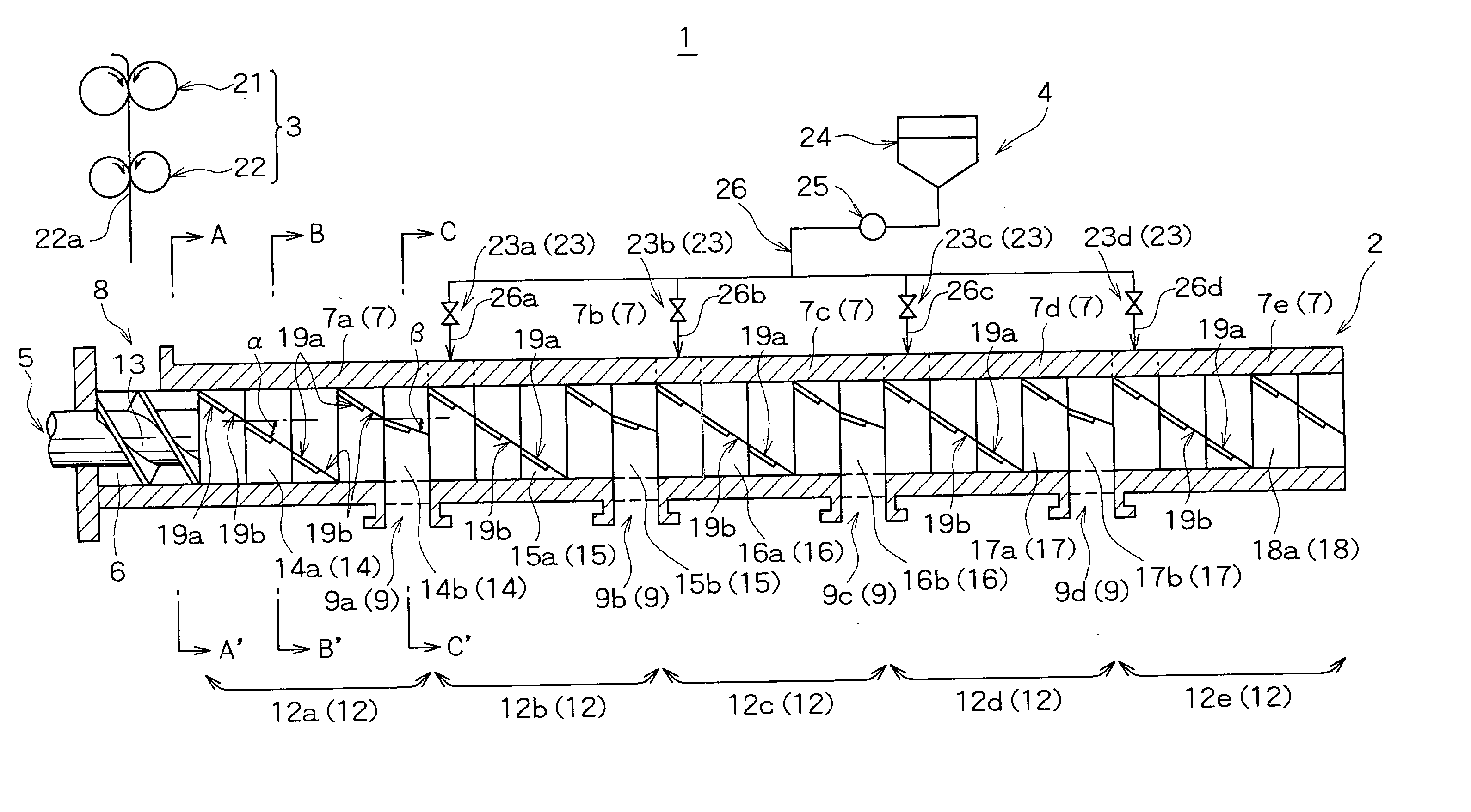
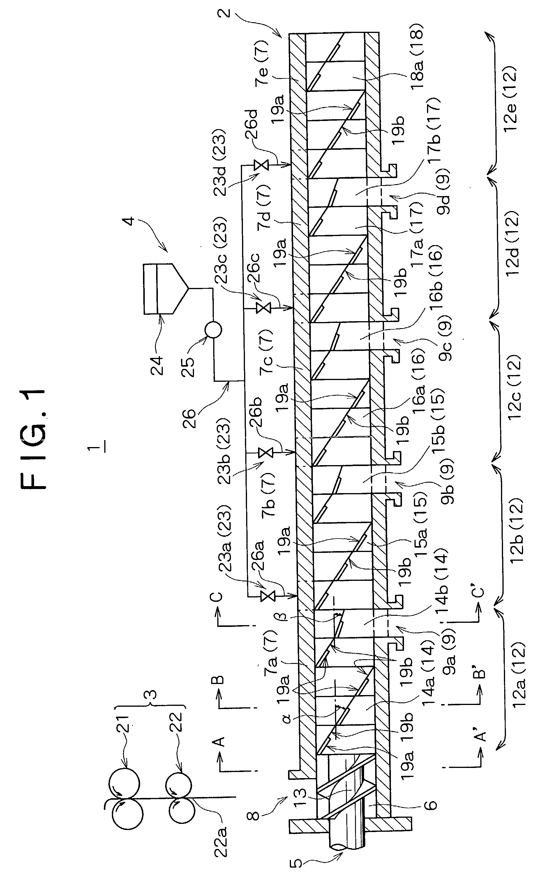
[0122] In this example, experiment of production of a kneaded product was conducted by using the kneading apparatus 31 (refer to FIG. 7) according to the embodiment of the present invention. As the double-screw kneading extruder 32, an extruder having a screw diameter of 59 mm, and a ratio (L / D) of the length of the screw set 35 to the screw diameter of 36 was used. In the description below, the axial length of the barrel 37 is represented by a L / D value (for example, a portion with a L / D of 48 from the upstream side of the barrel 37 represents a middle position of the barrel 37 in the axial direction). During kneading, cooling water was passed through the cooling liquid paths 41 provided in the barrel 37 so that the barrel temperature was controlled to be maintained at about 30.degree. C. during kneading, and a kneaded product was discharged as a block from the end 37a of the barrel 37.

[0123] As the position of the charging port 39 for supplying the material to be kneaded, the char...


PUM

PropertyMeasurementUnit
temperatureaaaaaaaaaa
twist anglesaaaaaaaaaa
timeaaaaaaaaaa

Abstract

A continuous kneading apparatus and method are provided wherein discharge ports are provided at a plurality of positions of the barrel to discharge a kneaded product, and one of the plurality of the discharge ports is selected according to a desired kneading condition so as to discharge the kneaded product from only the selected discharge port. Another continuous kneading apparatus and method are provided wherein a plurality of charging ports are provided at a plurality of positions of the barrel to supply a material to be kneaded into the chamber, and one of the plurality of charging ports is selected according to a desired kneading condition. The kneading apparatuses and methods permit adjustment and control of a viscosity and a dispersion degree of a compounding agent over a wide range, and continuous kneading to achieve significant rationalization of a process for producing a kneaded product.

Description

[0001] 1. Field of the Invention[0002] The present invention relates to an apparatus and method for kneading rubber or a rubber composition, for the purpose of masticating rubber to improve fluidity and workability, and the purpose of kneading a material to be kneaded, which contains rubber and various compounding agents.[0003] 2. Description of the Related Art[0004] In producing a kneaded product of a rubber composition comprising rubber and various compounding agents, particularly in producing a tire rubber compound mainly comprising natural rubber, a batch system is frequently used, in which predetermined amounts of raw materials are intermittently kneaded one time each. In this case, batch-system kneading is repeated until extrusion workability and a degree of dispersion of a compounding agent reach desired levels, i.e., desired levels of viscosity and of dispersion are obtained. This kneading step is generally referred to as a "re-milling step", and uses a batch-system kneading...

Claims


Application Information

Patent Timeline
Patent Type & Authority Applications(United States)
IPC IPC(8): B01F15/02B29B7/48B29B7/58B29B7/60B29B7/74B29C48/03B29C48/40B29C48/405B29C48/65
CPCB01F15/0267B29B7/48B29B7/582B29C47/625B29B7/7495B29C47/0009B29C47/60B29B7/60B29C48/03B29C48/65B29C48/405B29C48/40B01F35/751
Inventor MURAKAMI, MASAOYAMADA, NORIFUMIINOUE, KIMIO
Owner KOBE STEEL LTD
Why Eureka
Try Eureka