
Transmit power control for multiple rate wireless communications

a wireless communication and transmission power technology, applied in power management, transmission monitoring, receiver monitoring, etc., can solve the problems of less redundancy information, less robustness, and increased transmit power, and achieve less than optimal use of default values

Inactive Publication Date: 2003-06-19
INTELLECTUAL VENTURES I LLC
View PDF4 Cites 102 Cited by
  • Summary
  • Abstract
  • Description
  • Claims
  • Application Information

AI Technical Summary

Problems solved by technology

Increases in required transmit power is a necessary consequence of increased path loss in the 5 GHz band.
Also, a higher data rate for a given constellation type using less redundancy information is more sensitive to distortion and therefore less robust.
The problem arises as to how to efficiently maintain closed-loop power control in a radio (such as an AP or the like) that transmits multiple data rate packets at multiple output power levels.
The use of default values carry the penalty of being less than optimal since conservative assumptions must be made.
A more severe concern is that the radio may drift over time causing significant distortion and errors.
Without closed loop control, unconstrained power drifts may cause spectral violations and bleed-over into adjacent channels thereby interfering with other users.
The power amplifier, however, is a non-linear device.
In this manner, a single control loop is insufficient to achieve the optimal power set point for each constellation type or data rate and separate loops would otherwise be required.
Separate control loops contribute to the complexity and cost of radio devices.
Furthermore, certain data rates may only be used infrequently so that significant drift may lead to significant error over time.
In other words, infrequently used loops exhibit significant errors and inefficient operation.
Higher data rates using more complex constellation types and / or encoding schemes are less tolerant to distortion and more likely to be power-limited based on maximum allowable distortion levels.

Method used


Image

  • Transmit power control for multiple rate wireless communications
  • Transmit power control for multiple rate wireless communications
  • Transmit power control for multiple rate wireless communications

Examples


Embodiment Construction

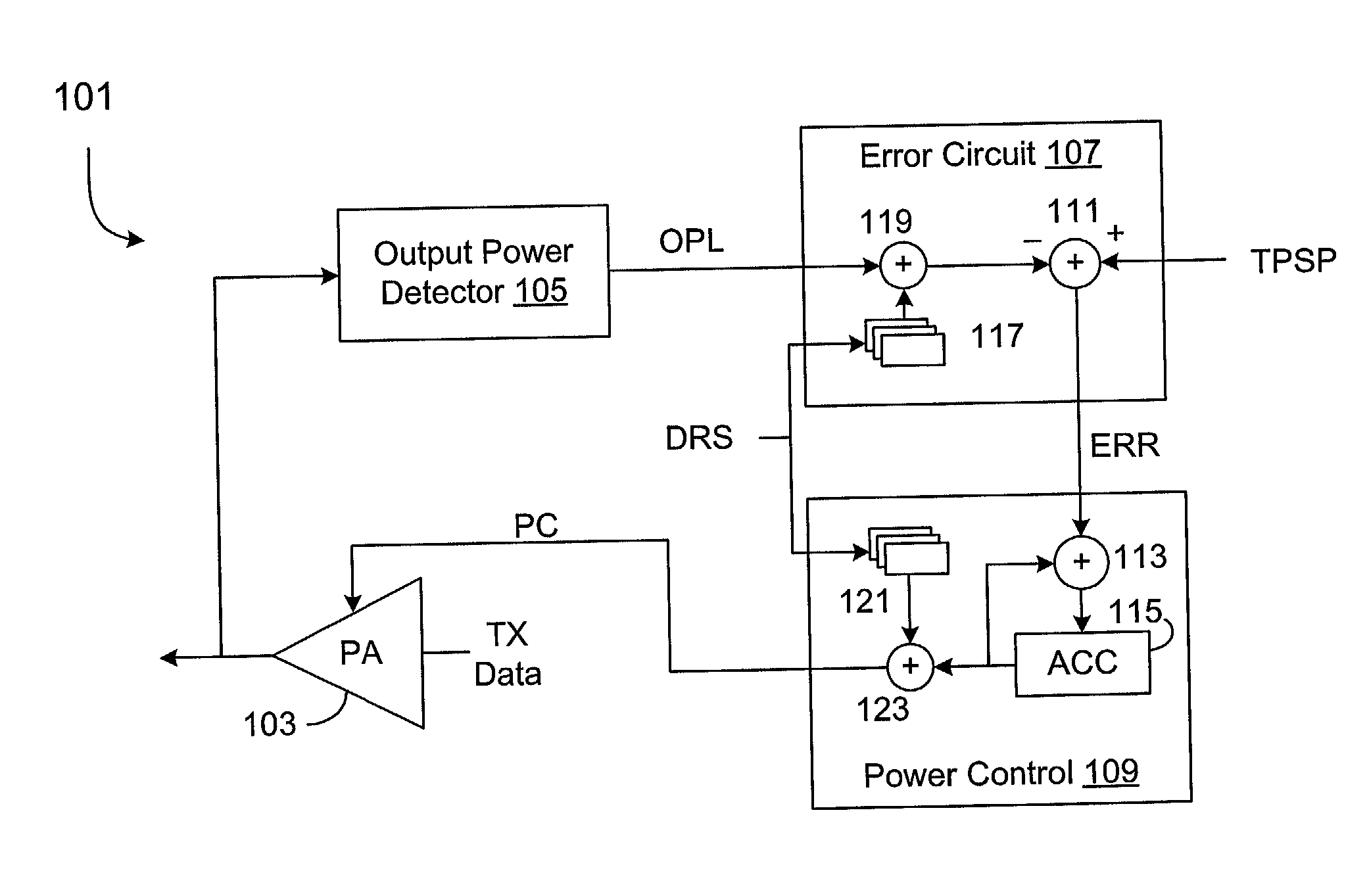
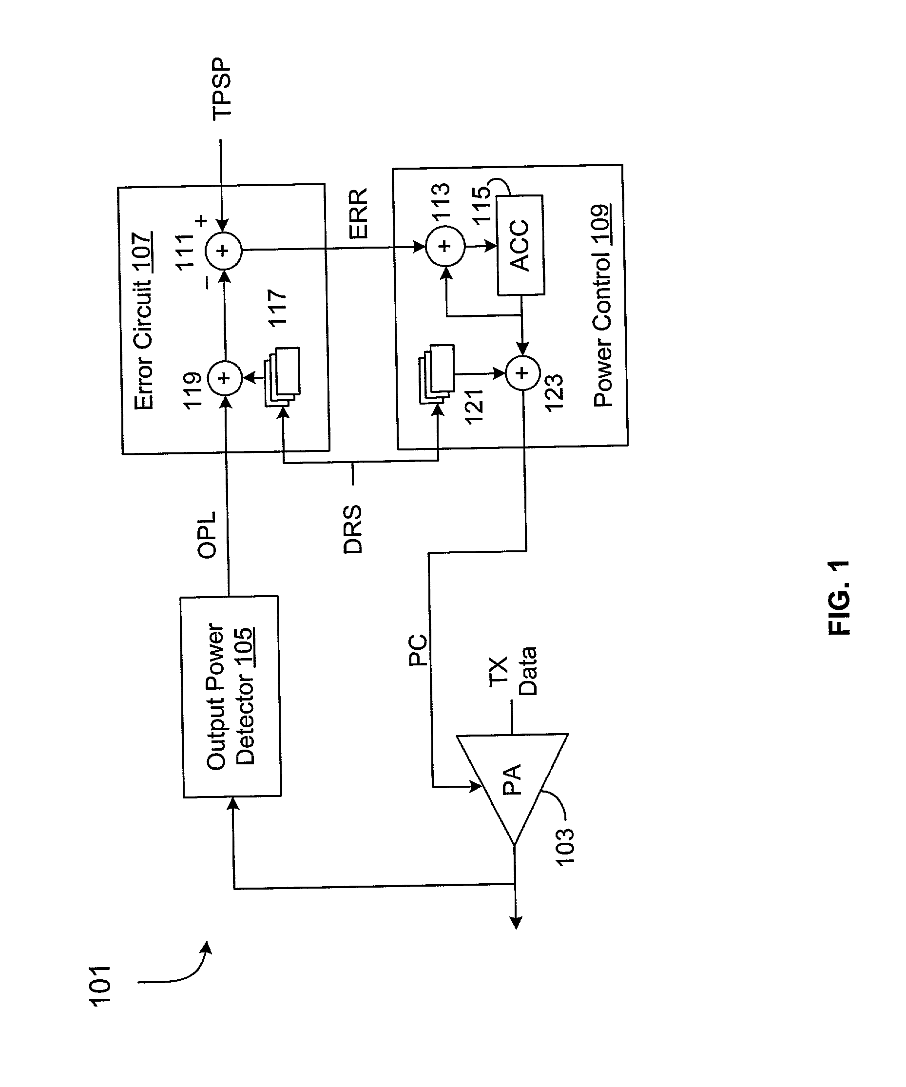
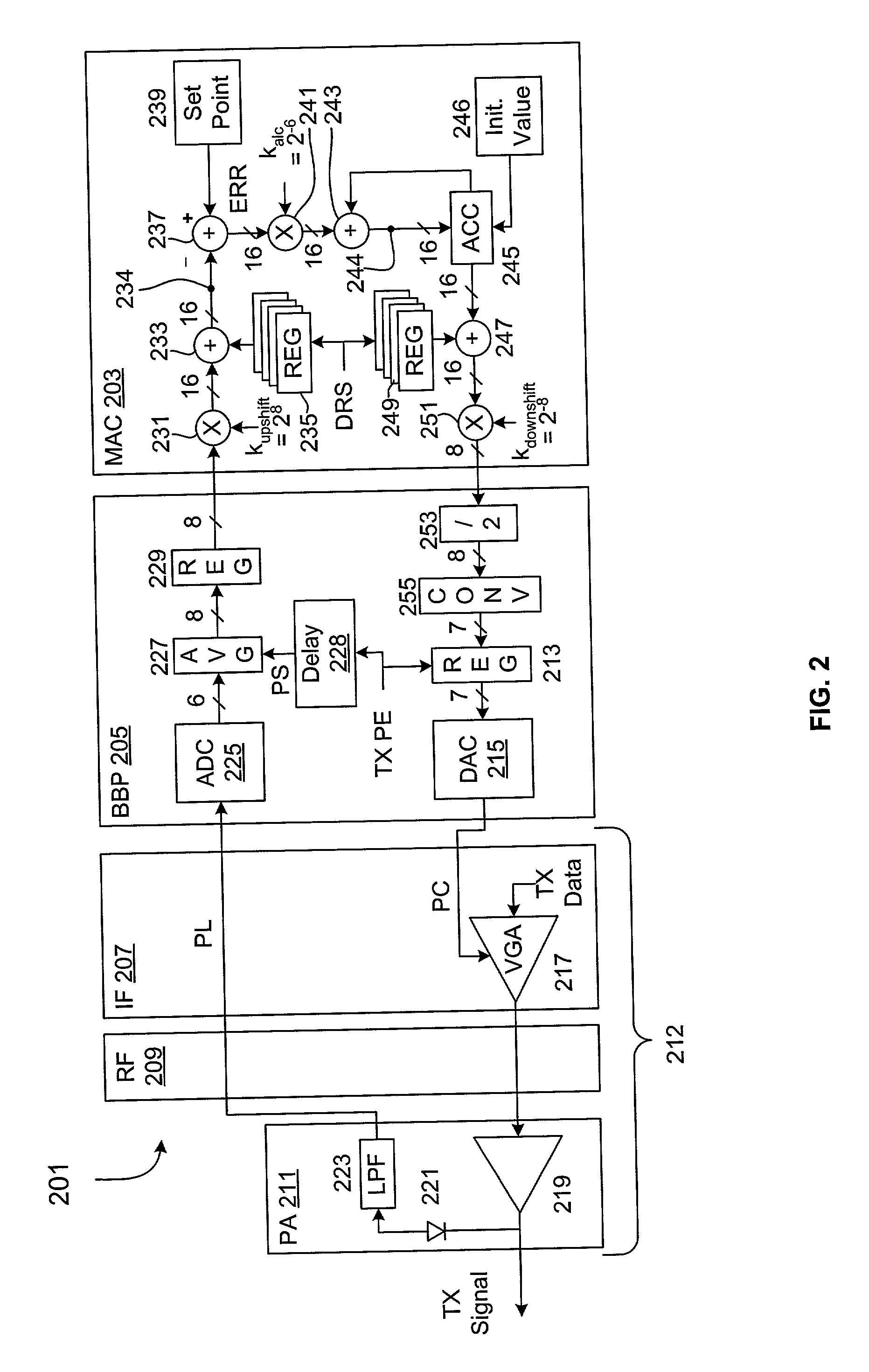
[0023] FIG. 1 is a block diagram of an exemplary transmit power control loop 101 according to an embodiment of the present invention. Transmit circuitry (not shown) develops a Transmit (TX) Data signal that is applied to the input of a power amplifier (PA) 103 for transmission in a wireless medium. An output power detector 105 is coupled to detect the output power level of the PA 103 and for generating a corresponding output power level (OPL) value indicative thereof. The OPL value is provided to an error circuit 107, which compares (or otherwise combines) the OPL value with a target power set point value TPSP and generates a corresponding error value ERR. In one embodiment, the error circuit 107 includes a summing junction 111 that subtracts the OPL value from the TPSP value to provide the ERR value. The ERR value is provided to a power control circuit 109, which uses the ERR value to adjust a power control signal PC. In one embodiment, the power control circuit 109 includes a summ...


PUM


Abstract

An RF device including a control loop for maximizing output power for each of several data rates or constellation types. The RF device includes a power detector, a power amplifier and a MAC that includes input and output adjust circuits. A power level value is generated from measured output power. The MAC compares an adjusted power level value with a set point value and generates an error value. The MAC adjusts a power control value based on the error value for controlling the gain of the power amplifier. The MAC uses a data rate signal indicative of a selected constellation type or data rate. The input adjust circuit stores one or more input adjustment values selected by the data select signal for adjusting the power level value. The output adjust circuit stores one or more output adjustment values selected by the data select signal for adjusting the power control value.

Description

[0001] The present invention relates to wireless communications, and more particularly to an efficient multiple data rate, closed-loop transmit power scheme for wireless packet communications.DESCRIPTION OF RELATED ART[0002] The data rate of wireless data communications, including Wireless Local Area Networks (WLANs) and associated devices, continue to increase. Methods of increasing data rate includes different coding schemes and higher capacity modulation schemes. Exemplary modulation schemes include Binary Phase Shift Keying (BPSK), Quadrature PSK (QPSK), 16 Quadrature Amplitude Modulation (QAM), and 64 QAM employing corresponding constellation types with 2, 4, 16 or 64 constellation points, respectively, for modulating 1, 2, 4 or 6 bits, respectively. BPSK uses a relatively low capacity constellation type whereas 64 QAM uses a relatively high capacity constellation type. The Institute of Electrical and Electronics Engineers, Inc. (IEEE) 802.11a standard employs the BPSK, QPSK, 1...

Claims


Application Information

Patent Timeline
IPC IPC(8): H04B7/005H04B17/00
CPCH04W52/267H04B17/21H04W52/52
Inventor BALDWIN, KEITH R.
Owner INTELLECTUAL VENTURES I LLC
Learn More