
Broadband optical fiber

a broadband optical fiber and optical fiber technology, applied in the field of broadband optical fiber, can solve the problems of low raman amplification efficiency, uneconomical optical fiber, and deterioration of signal-to-noise characteristic (snr)

Inactive Publication Date: 2003-06-26
FURUKAWA ELECTRIC CO LTD
View PDF4 Cites 12 Cited by
  • Summary
  • Abstract
  • Description
  • Claims
  • Application Information

AI Technical Summary

Benefits of technology

[0017] The present invention has an object to provide an optical fiber particularly suitable for the Raman amplification.

Problems solved by technology

However, the effective area (A.sub.eff) of the SMF is around 80 .mu.m.sup.2, relatively large; and its Raman amplification efficiency is low.
Consequently, there is a problem that this optical fiber is uneconomical.
Also, the signal-to-noise characteristic (SNR) tends to be deteriorated.
However, the occurrence of another nonlinear phenomenon due to the input of high-power light becomes a problem.
Consequently, it is required to suppress a bit error rate (BER) to an extremely low level, so that if there exists the nonlinear phenomenon problem described above, it becomes difficult to apply the NZDSF to the Raman amplification in the DWMD transmission system.
However, the efficiency of the optical fiber disclosed in JP 11-84159 A is still low from the viewpoint of providing the Raman amplification, although the efficiency is not so low when compared with the SMF described above.
Therefore, it is impossible to significantly reduce the total power of the wavelength multiplexed pumping light source, so that the uneconomical problem still remains.
That is, each optical fiber described above is not suitable for providing an optical transmission system with the Raman amplification.

Method used


Image

  • Broadband optical fiber
  • Broadband optical fiber
  • Broadband optical fiber

Examples


examples of embodiment

[0057] (Examples of Embodiment)

[0058] The present invention will be described in detail below based on specific examples.

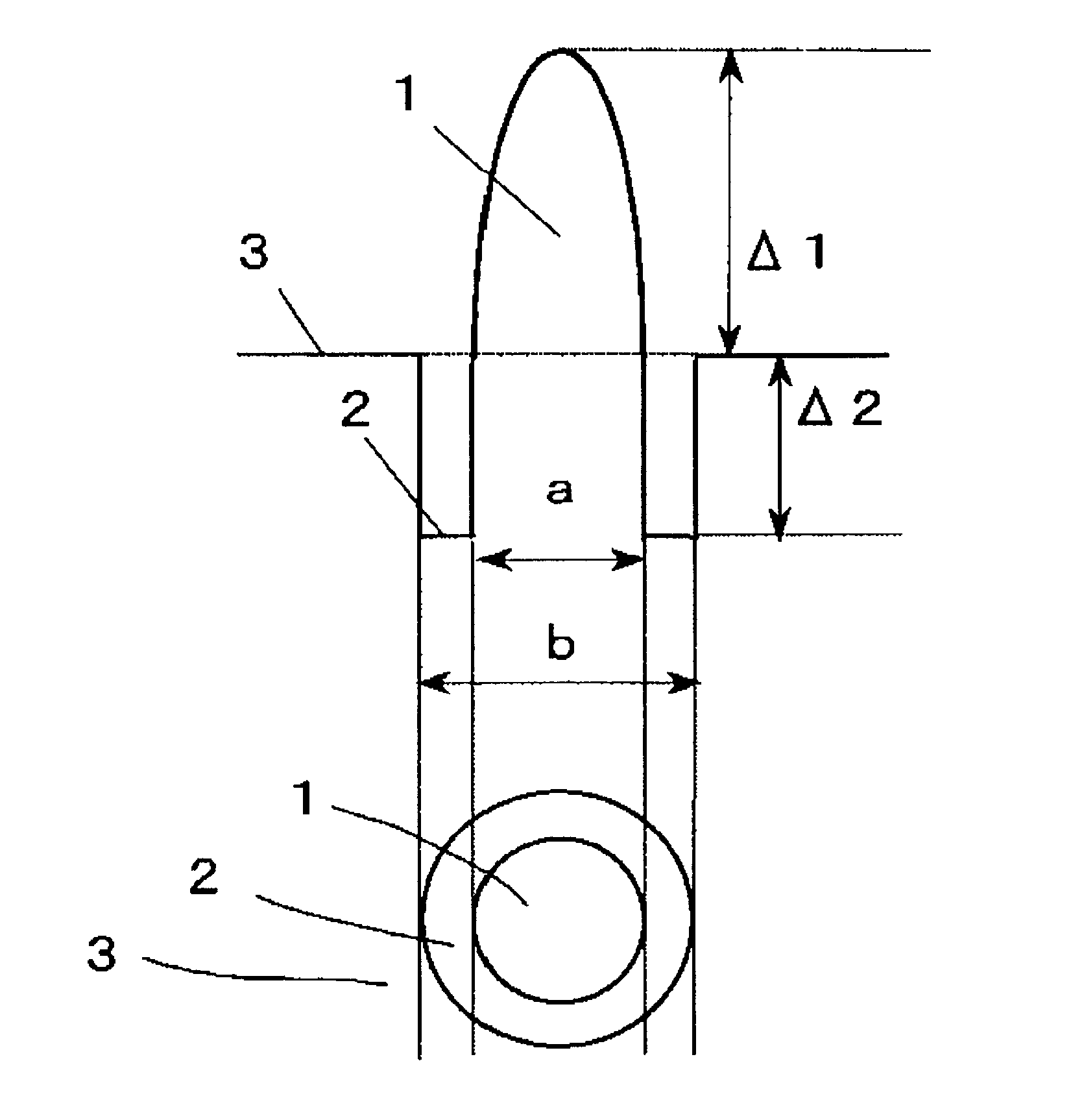
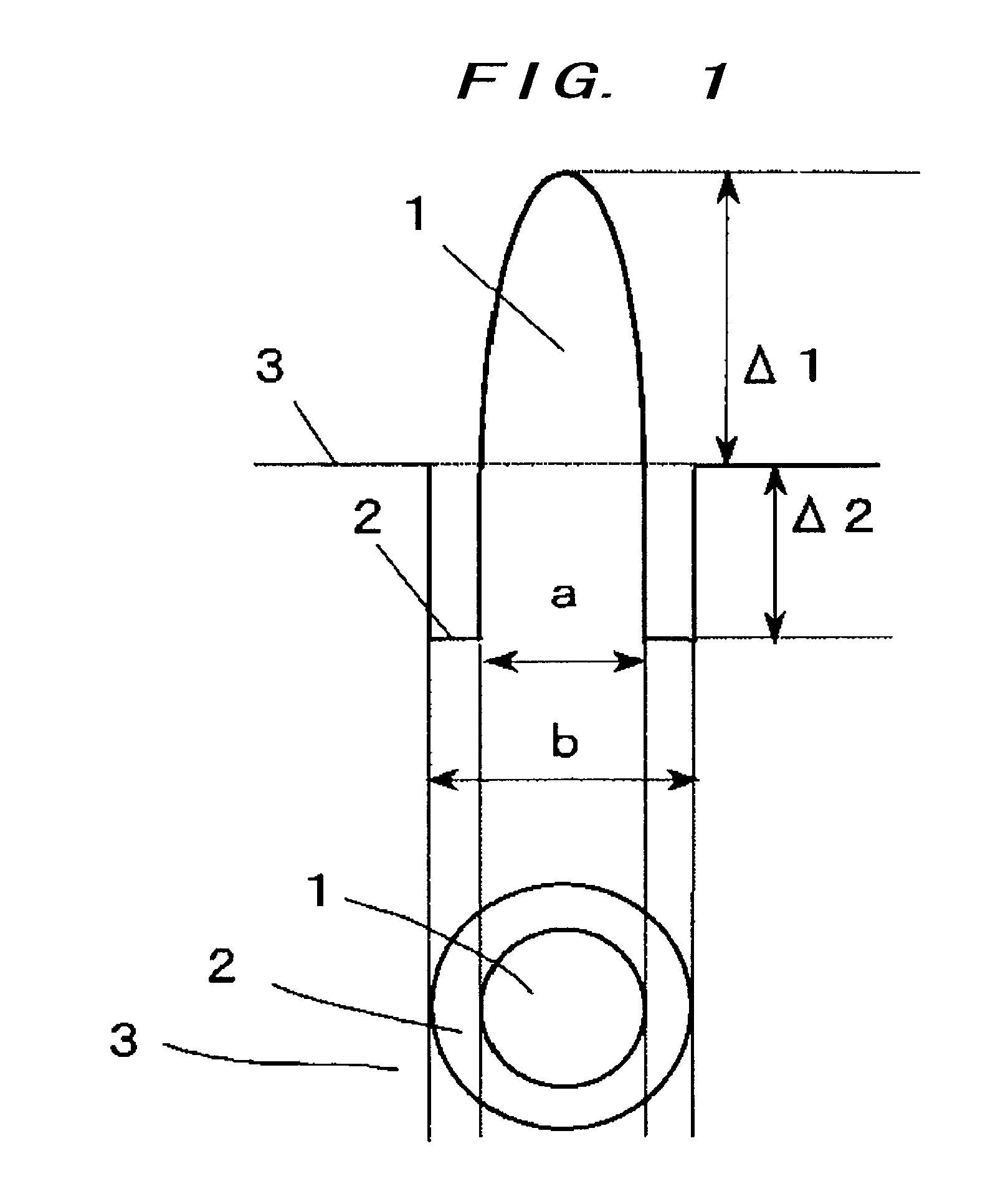
[0059] Optical fibers of examples of embodiment according to the present invention and an optical fiber of a comparative example are shown in Table 1. Note that the unit of .DELTA.1 and .DELTA.2 is %, the unit of the outside diameter "b" of an annular region ("b" is cladding inside diameter for the comparative example) is um, the unit of dispersion is ps / nm / km, the unit of the dispersion slope is ps / nm.sup.2 / km, the unit of the cutoff wavelength .lambda..sub.c and the zero-dispersion wavelength .lambda..sub.0 is nm, and the unit of A.sub.eff is .mu.m.sup.2. The values of the dispersion, dispersion slope, and A.sub.eff being values are obtained at the wavelength of 1570 nm.

1 TABLE 1 Dispersion .DELTA.1 .DELTA.2 b / a b Dispersion slope .lambda..sub.c .lambda..sub.o A.sub.eff Example 1 0.63 -0.65 1.30 10.30 8.4 0.026 971 1365 40 Example 2 0.63 -0.70 1.30 10.00 5.8 0.0...


PUM


Abstract

Provided is an optical fiber that is in particular suitable for Raman amplification. An effective area at a wavelength of 1570 nm is in a range of 35 mum2 to 45 mum2, an absolute value of a dispersion slope at the wavelength is equal to or less than 0.04 ps / nm2 / km, and a dispersion value at the wavelength is in a range of 5 ps / nm / km to 10 ps / nm / km. It is desirable that a refractive index profile contains at least one annular region between a center core and a cladding region.

Description

[0001] The present invention relates to an optical fiber that is suitably used for wavelength division multiplexing (WDM) optical transmission system.RELATED ART[0002] An optical fiber with a primary silica content and a germanium-doped core is in widespread use. For increasing the transmission capacity of optical fiber in action, a technique of performing WDM optical transmission is actively studied. In recent years, an optical transmission system using Raman amplification is also studied.[0003] As to the Raman amplification, it is known that the maximum value of a Raman gain is obtained some 100 nm on the longer wavelength side with reference to a pumping light source wavelength. By utilizing this phenomenon, an attempt has been made to amplify WDM signal light with a plurality of pumping light sources having different wavelengths (hereinafter referred to as the "wavelength multiplexed pumping light source").[0004] Here, in order to prevent the pumping light on the longest wavelen...

Claims


Application Information

Patent Timeline
IPC IPC(8): G02B6/036G02F1/35
CPCG02B6/02009G02B6/02028G02B6/02242H04B2210/003G02B6/03627H04B10/2916G02B6/02271
Inventor SHIBUTA, TAEKO
Owner FURUKAWA ELECTRIC CO LTD
Learn More