

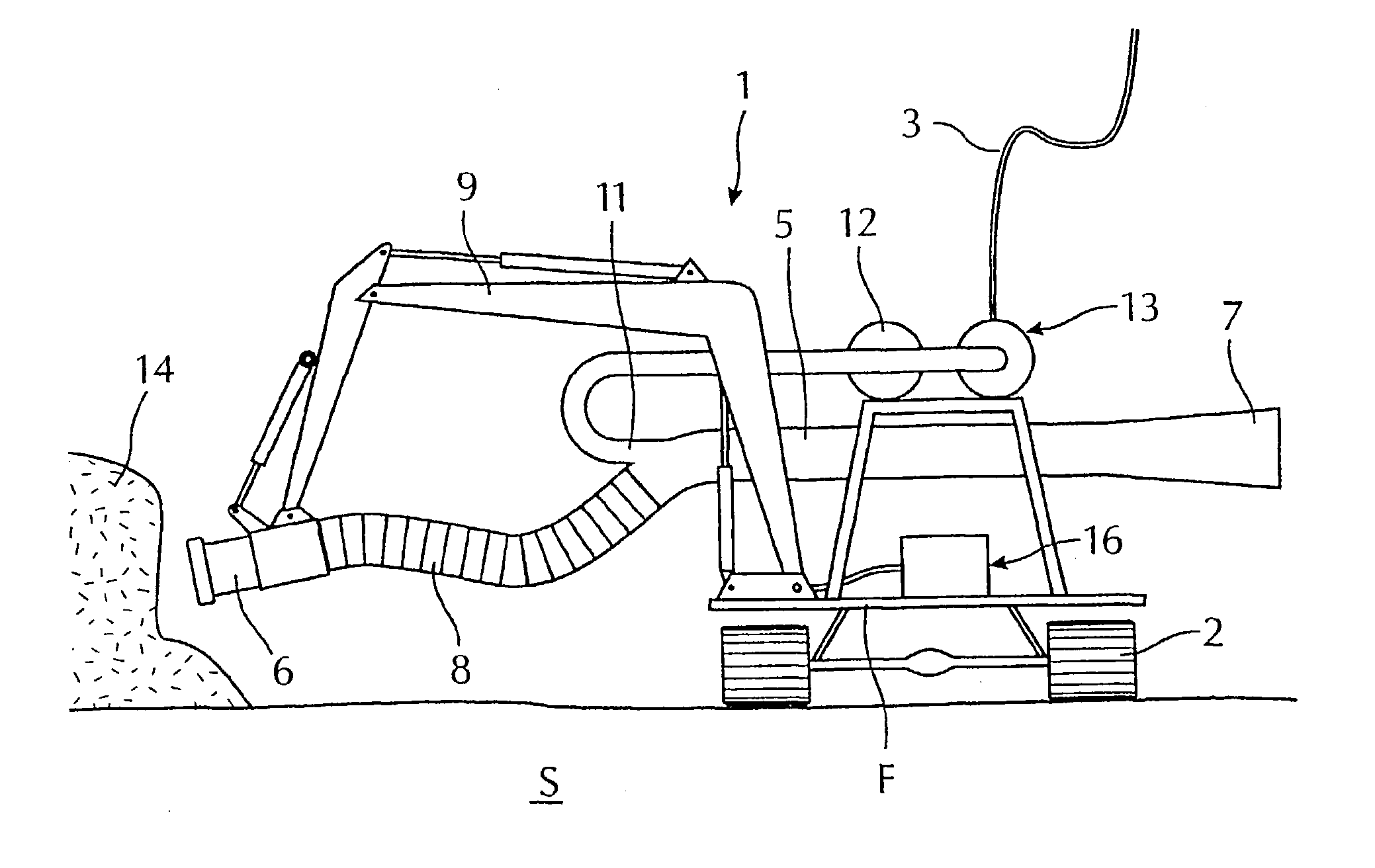
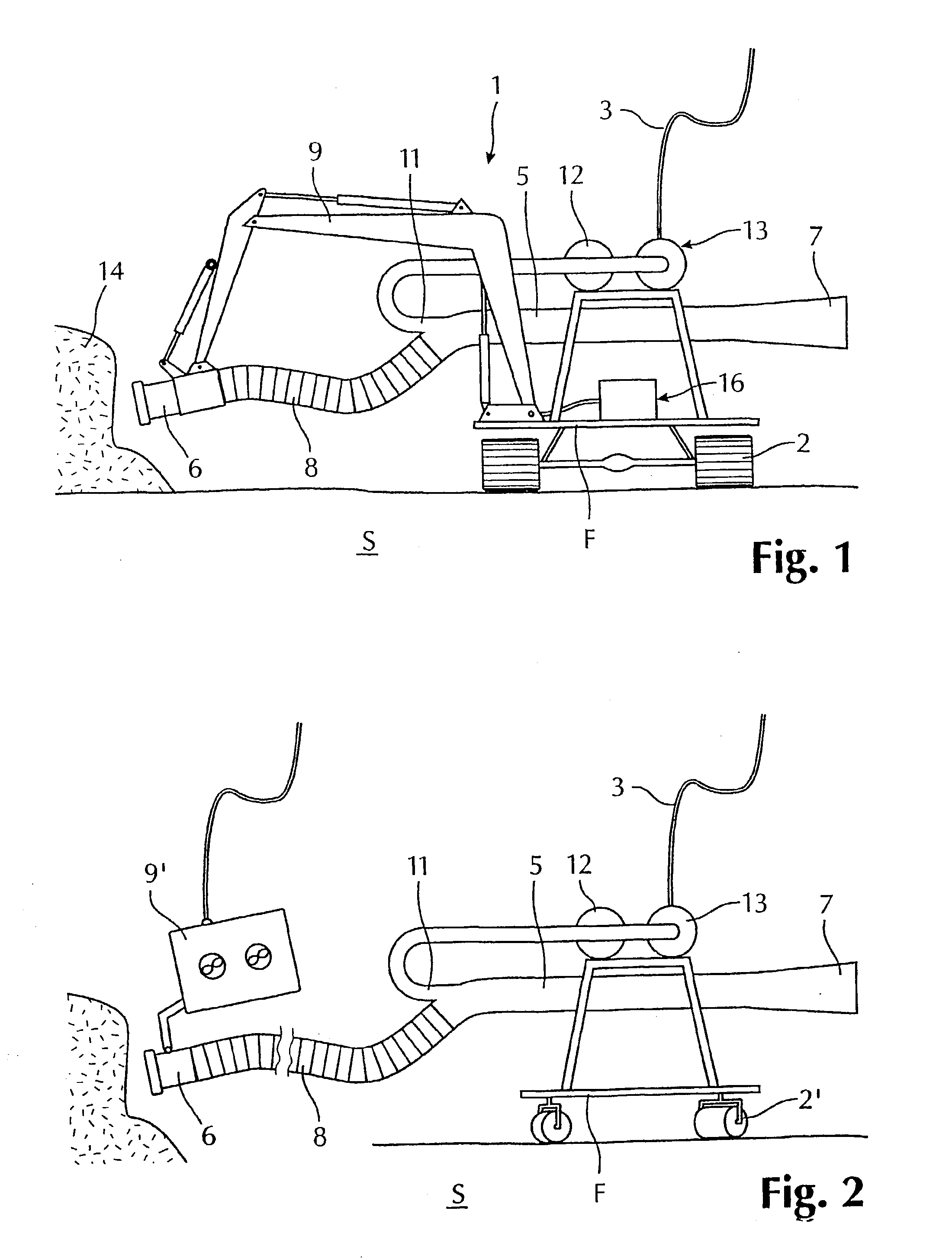
Method and device for subsea dredging
a technology for subsea dredging and submerged water, which is applied in the field of methods and devices for subsea dredging, can solve the problems of large surface vessels, high power consumption of specially designed excavators, and large power consumption of special equipment, and achieves a constant cross-section of tubing, reduce frictional loss through tubing, and reduce the effect of frictional loss
- Summary
- Abstract
- Description
- Claims
- Application Information
AI Technical Summary
Benefits of technology
Problems solved by technology
Method used
Image

Examples
Embodiment Construction
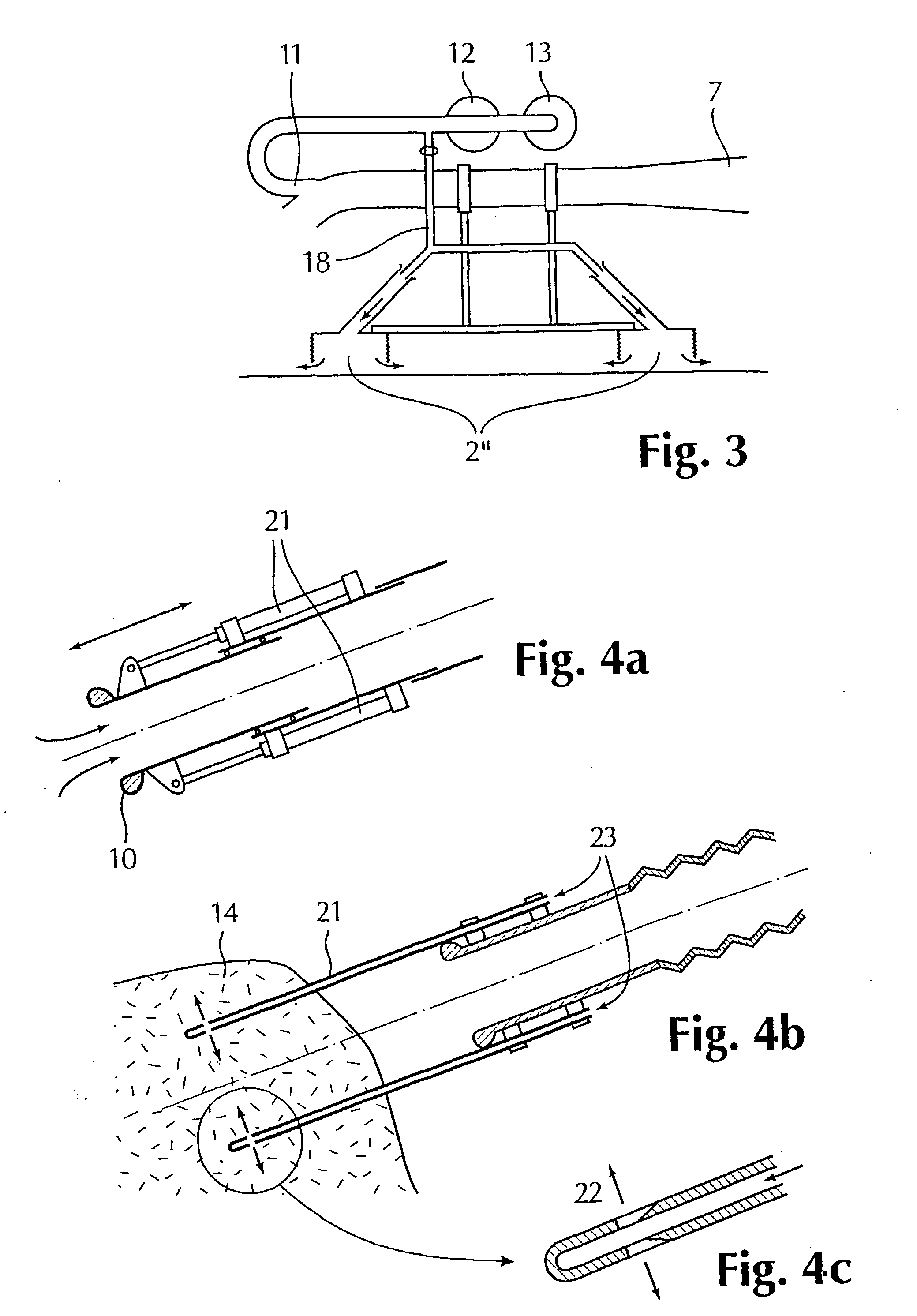
[0027] In the following example of utilization there is an assumption of one or two water pumps each powered by a motor of 75 kW. It is assumed that the tubing has an internal diameter of 300 mm. In the case of two pumps there is also conducted calculations for a 500 mm tubing. Further data are given in the table below.
1 Motor power (axle-) kW 75 150 150 Power efficiency % 80 80 80 Internal diameter mm 300 300 500 Length (inlet-outlet) m 15 15 12 Speed prior to mixing m / s 5.8 7.4 5.9 chamber Required speed m / s 4.4 4.4 5.7 Motive power m 2.5 4.2 1.8 (lifting height) of which inlet loss is m 0.3 0.6 0.4 frictional loss is m 1.4 2.3 0.7 outlet loss is m 0.7 1.3 0.7 Ca. capacity transport rocks tons / hour 70 120 100
PRACTICAL EXAMPLE
[0028] A commission conducted shows that the invention works in practice. During the summer of 1999, 1500 m.sup.3 (d.sub.max=ca. 150 mm) of rocks were moved with the aid of a corresponding ejector mechanism, carried by a remotely operated vehicle, ROV. The com...
PUM
 Abstract
Description
Claims
Application Information