Discharge lamp lighting apparatus

a technology of lighting apparatus and discharge lamp, which is applied in the direction of electric variable regulation, process and machine control, instruments, etc., can solve the problems of increasing the cost of manufacturing the discharge lamp lighting apparatus, and requiring expensive circuit elements, etc., and achieves the effect of simple circuit construction

Inactive Publication Date: 2003-07-03
TOSHIBA LIGHTING & TECH CORP
View PDF3 Cites 14 Cited by
  • Summary
  • Abstract
  • Description
  • Claims
  • Application Information

AI Technical Summary

Benefits of technology

[0007] This invention has an object to provide a discharge lamp lighting apparatus which is able to control the lighting state of discharge lamps in a simple circuit construction.
[0009] According to the first aspect of the discharge lamp lighting apparatus, it is able to indirectly determine the lighting state of the discharge lamp according to the high frequency current, which is induced in the detection winding of the transformer and then supplied to the second DC power supply circuit. Therefore, the configuration of the discharge lamp lighting apparatus can be simplified, due to that there is no necessity of providing a specific lighting state monitor.
[0011] According to the second aspect of the invention, the lamp voltage determiner is able to indirectly determine the lamp voltage of the discharge lamp according to the DC supply voltage of the second DC power supply circuit. Therefore, there is no necessity of providing a lamp voltage determiner in the inverter circuit, and thus the discharge lamp lighting apparatus can be simplified.
[0013] According to the third aspect of the invention, a starting operation for the discharge lamp upon turning-on the discharge lamp lighting apparatus can be securely carried out.
[0028] According to the tenth aspect of the discharge lamp lighting apparatus, a higher harmonic interference can be prevented by a low distortion feature and a high power factor feature of the boosting chopper regulator. According to the tenth aspect of the discharge lamp lighting apparatus, since the voltage of the second DC power supply circuit is secured from the detection winding of the transformer before the chopper operation switching element is started, a reliable operation of the second DC power supply circuit is guaranteed.

Problems solved by technology

Therefore, in this case there is a problem of increasing the cost for manufacturing the discharge lamp lighting apparatus.
In this case, expensive circuit elements are required.
Therefore, in this case there is also a problem of increasing the cost for manufacturing the discharge lamp lighting apparatus.
In this case, the circuit configuration becomes complicated by an increase of circuit elements.
Therefore, in this case there is also a problem of increasing the cost for manufacturing the discharge lamp lighting apparatus.
Therefore, this prior art has a problem of complicating the circuit configuration.

Method used


Image

  • Discharge lamp lighting apparatus
  • Discharge lamp lighting apparatus
  • Discharge lamp lighting apparatus

Examples


second embodiment

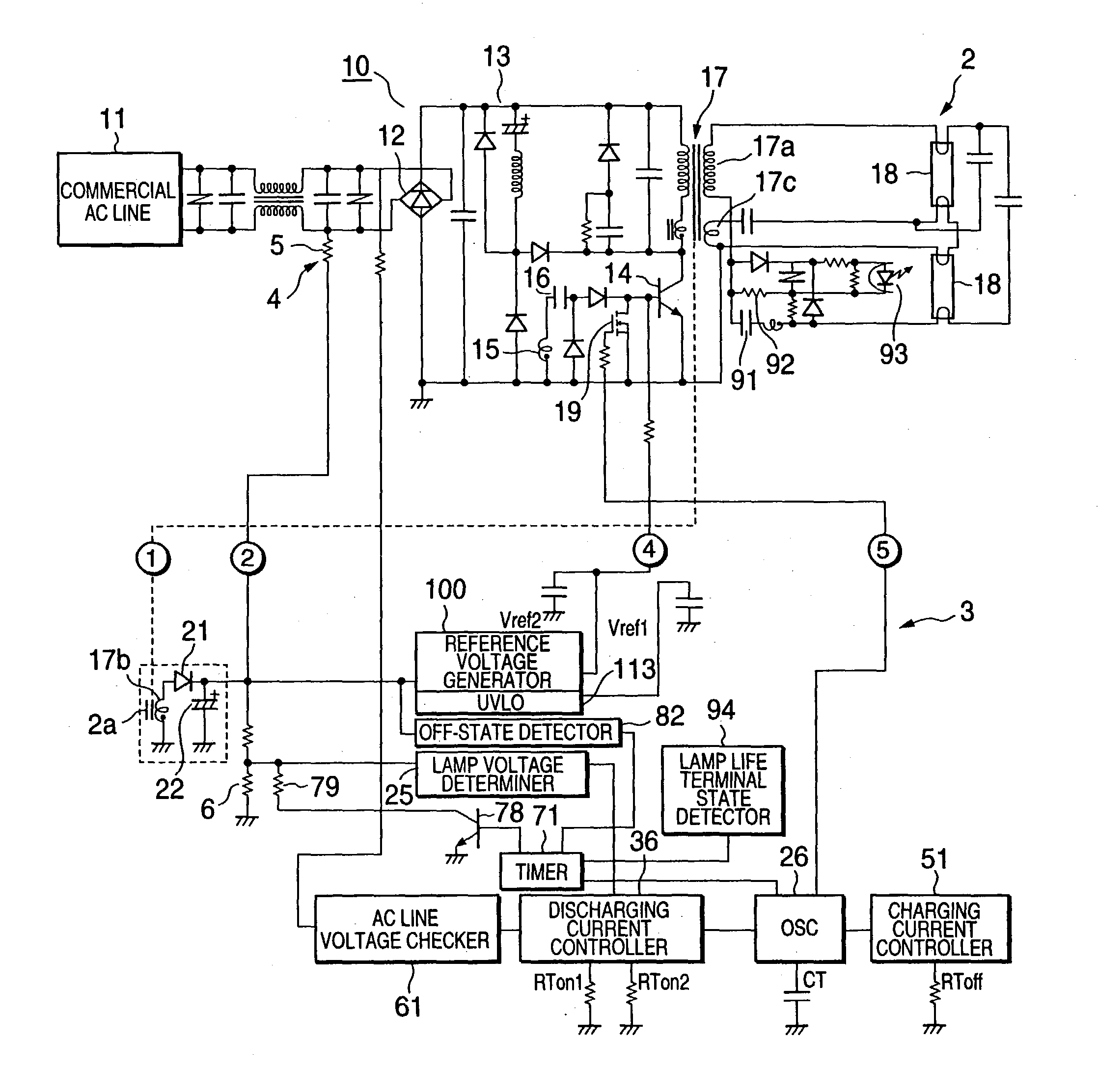
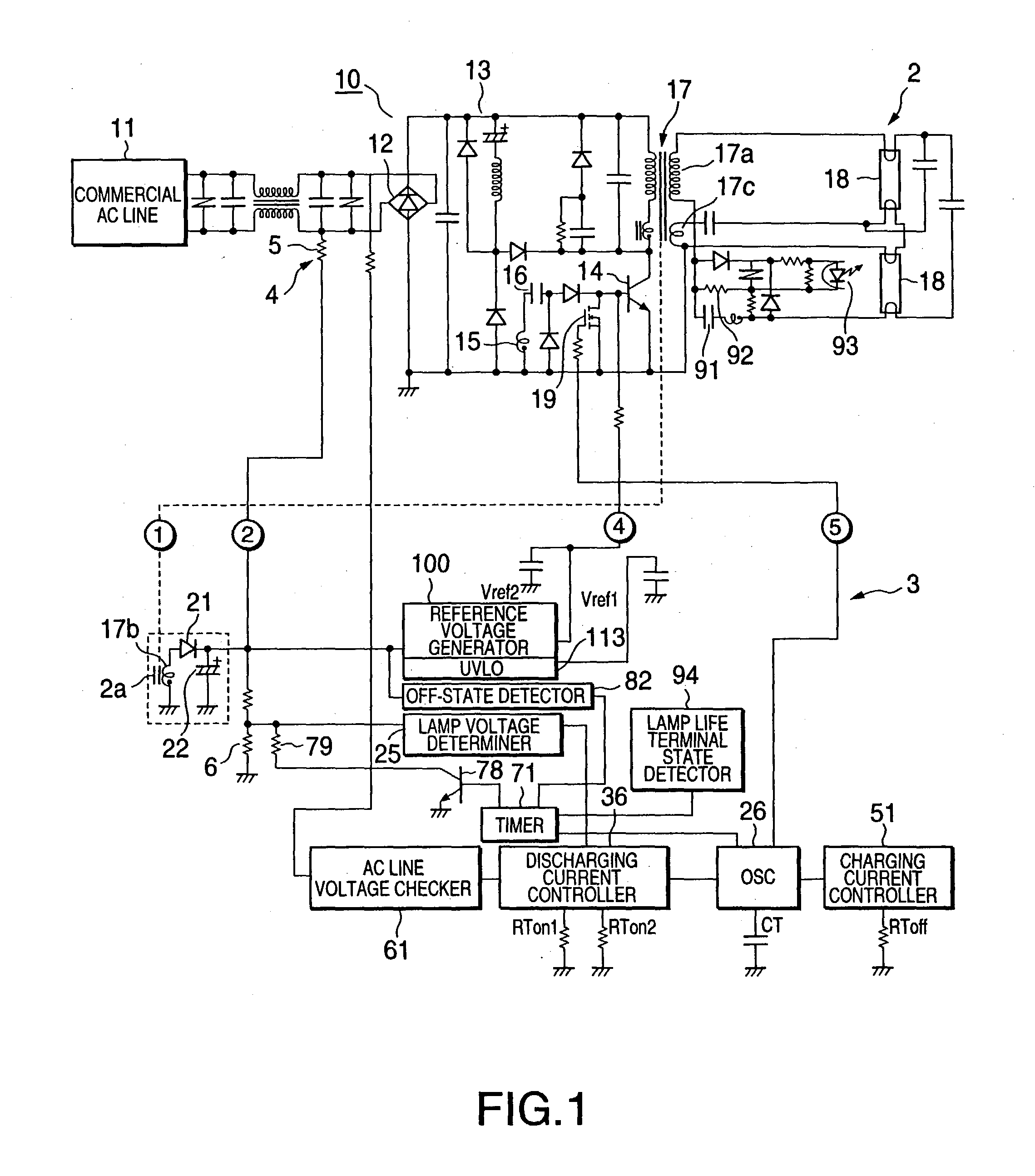
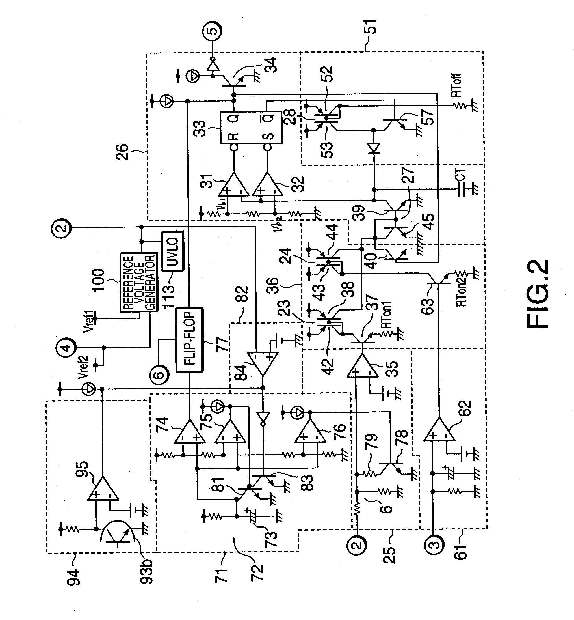
[0074] Referring now to FIGS. 6 and 7, the discharge lamp lighting apparatus according to the present invention will be described. FIGS. 6 and 7, respectively, illustrate an abridged configuration and a detailed configuration of the inverter controller 3. In FIGS. 6 and 7, the same or identical elements with those in FIGS. 1 and 2 are assigned with same reference numerals omitted their explanation.

[0075] The second embodiment has a principal construction the same as the first embodiment. The second embodiment is different from the first embodiment in that the off-state detector 82 is connected to the voltage divider 6 as well as the lamp voltage determiner 25.

[0076] According to the second embodiment, a circuit for generating the reference voltages and a circuit for detecting the lamp voltage and the off-state of discharge lamps can be separately connected to the second DC power supply circuit 2a. Therefore, a processing of the power-supply voltage Vcc obtained by the second DC powe...

third embodiment

[0077] Referring now to FIG. 8, the discharge lamp lighting apparatus according to the present invention will be described. In FIG. 8, the same or identical elements with those in FIG. 1 are assigned with same reference numerals omitted their explanation.

[0078] A Zener diode 121 is connected to the output end of the second DC power supply circuit 2a for limiting an excessive voltage from being output. The Zener voltage of the Zener diode 121 is set a value below the withstand voltage of the inverter controller 3.

[0079] Also in the third embodiment, the inverter controller 3, the starting circuit 4, and the second DC power supply circuit 2a, etc., have the same configuration and the same feature as those of the first and the second embodiments. For example, when an off-state of the discharge lamp is detected in the off-state detector 82 or the lamp life terminal state, i.e., a state of appearing a DC component caused by an unbalance between the positive and negative half-cycle discha...


PUM


Abstract

The invention provides a discharge lamp lighting apparatus. The apparatus comprises a first DC power supply circuit for converting an AC line voltage to a DC voltage, an inverter circuit provided with a switching element and a transformer, thereby the DC voltage supplied from the first DC power supply circuit is converted to a high frequency voltage for lighting a discharge lamp by an on-off switching operation of the switching element, an inverter controller for controlling the high frequency voltage output of the inverter by controlling the on-off switching operation of the switching element, a second DC power supply circuit for supplying a second DC voltage to the inverter controller through a power input end of the inverter controller, the second DC power supply circuit being provided with a detection winding inductively coupled to the transformer, thereby the second DC voltage being obtained by rectifying an induced current in the detection winding.

Description

2. FIELD OF THE INVENTION[0001] This invention relates to a discharge lamp lighting apparatus.[0002] This application is based upon and claims the benefit of priority from the prior Japanese Patent Applications No. 2001-399606, filed Dec. 28, 2001 and No. 2002-246786, filed Aug. 27, 2002.3. BACKGROUND OF THE INVENTION[0003] In this type of discharge lamp lighting apparatus, conventionally a lamp voltage is detected for controlling a voltage to be fed to a discharge lamp. Moreover, when the detected lamp voltage is abnormal, a control for delighting a discharge lamp is carried out. Conventionally, with this type of discharge lamp lighting apparatus, the lamp voltage was detected directly.[0004] Now, when parallel connection of two or more discharge lamps is made, with conventional apparatus, there is the necessity of providing a lamp voltage determiner for each discharge lamp of every. Therefore, in this case there is a problem of increasing the cost for manufacturing the discharge l...

Claims


Application Information

Patent Timeline
Patent Type & Authority Applications(United States)
IPC IPC(8): H05B41/24H05B41/282H05B41/285
CPCH05B41/2853Y02B20/186H05B41/2855Y02B20/00
Inventor KAMATA, MASAHIKOSHIMIZU, KEIICHISUGIYAMA, MASAHIROKOBAYASHI, KATSUYUKI
Owner TOSHIBA LIGHTING & TECH CORP
Why Eureka
Try Eureka