
Watercraft control mechanism

a control mechanism and watercraft technology, applied in the direction of propulsive elements, steering components, floating buildings, etc., can solve the problems of slow deceleration, watercraft susceptible to flooding and instability, and it is difficult for the rider to remain comfortably seated and in control of the steering handle or wheel

Inactive Publication Date: 2003-07-10
BOMBARDIER RECREATIONAL PROD INC
View PDF11 Cites 6 Cited by
  • Summary
  • Abstract
  • Description
  • Claims
  • Application Information

AI Technical Summary

Benefits of technology

[0018] It is a still further object of the invention to provide a watercraft control mechanism that decelerates or assists in decelerating a watercraft in a smooth and stable manner when the watercraft is travelling at high speeds.

Problems solved by technology

Deceleration by reversing thrust is the most common technique, but the deceleration is slow due to the time lag required to stop and then reverse the propeller.
The sudden diving of the bow makes the watercraft susceptible to flooding and instability and makes it difficult for the rider to remain comfortably seated and in control of the steering handle or wheel.
The flaps pivot such that the trailing edge is lower than the leading edge, thereby creating an undesirable elevating force at the stern.
Differential declination of the control flaps results in trimming and steering of the watercraft.
During braking, however, the downward sweep of the control flaps causes the stern of the watercraft to rise and the bow to dive, creating the potential for flooding and instability.
Diving of the bow is uncomfortable for the rider and makes control of the watercraft during hard braking maneuvers more difficult.
The scooping action of the vanes induces a great deal of turbulence on the underside of the watercraft, especially when braking at high speeds.
The amount of water that is channeled through the ducting system is also minimal and thus braking might, in some conditions, be too harsh.
The vanes and their associated attachment bases on the underside of the watercraft create drag at high speeds, even when fully retracted.
Large gears must also be provided to retract and close the vanes when they are scooping water which adds weight to the rear of the watercraft and causes the rear of the watercraft to sag.

Method used


Image

  • Watercraft control mechanism
  • Watercraft control mechanism
  • Watercraft control mechanism

Examples


Embodiment Construction

[0061] Various exemplary embodiments of watercraft including watercraft control mechanisms according to the present invention will be described with reference to the drawings, wherein like reference numbers describe like features.

[0062] As used throughout the following, the use of terms such as "front", "forward", "back", "rearward", "top", and "bottom" refer to the situation when the watercraft is in the upright position travelling in a forward direction.

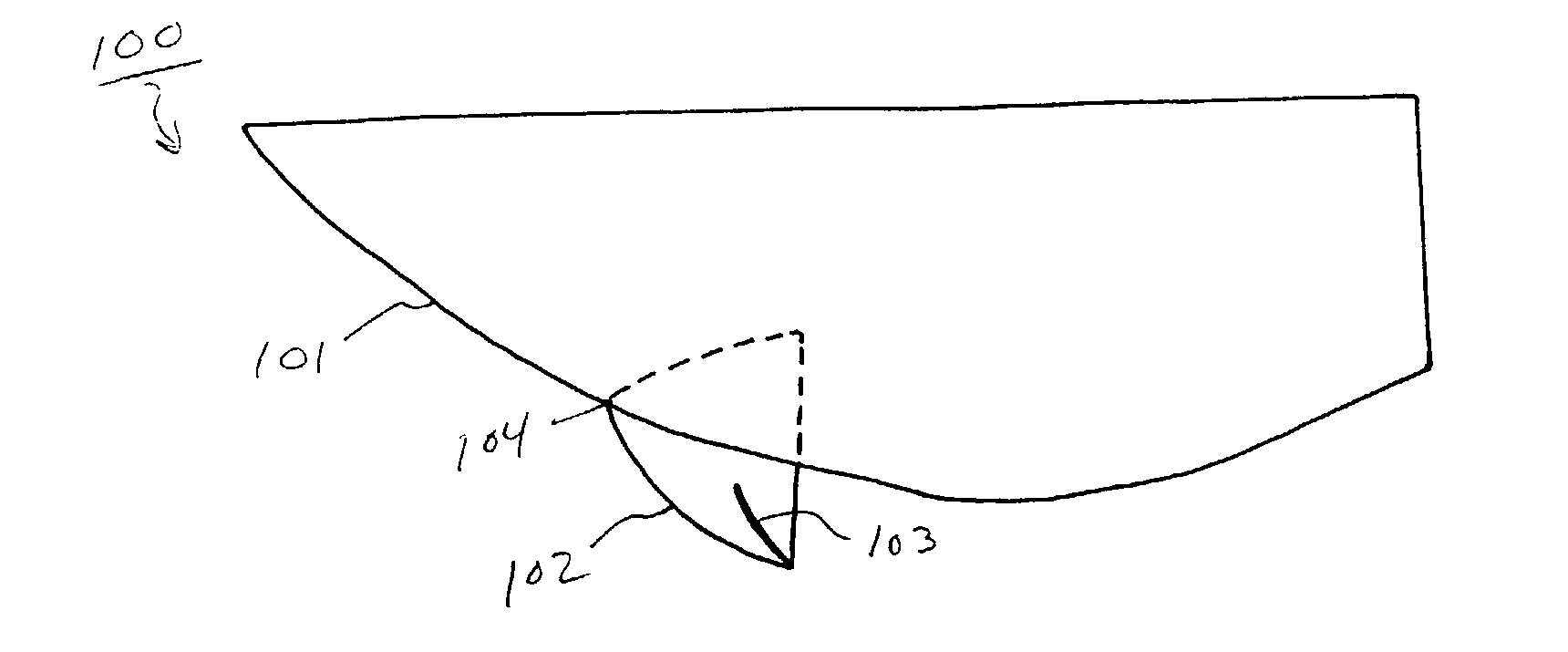
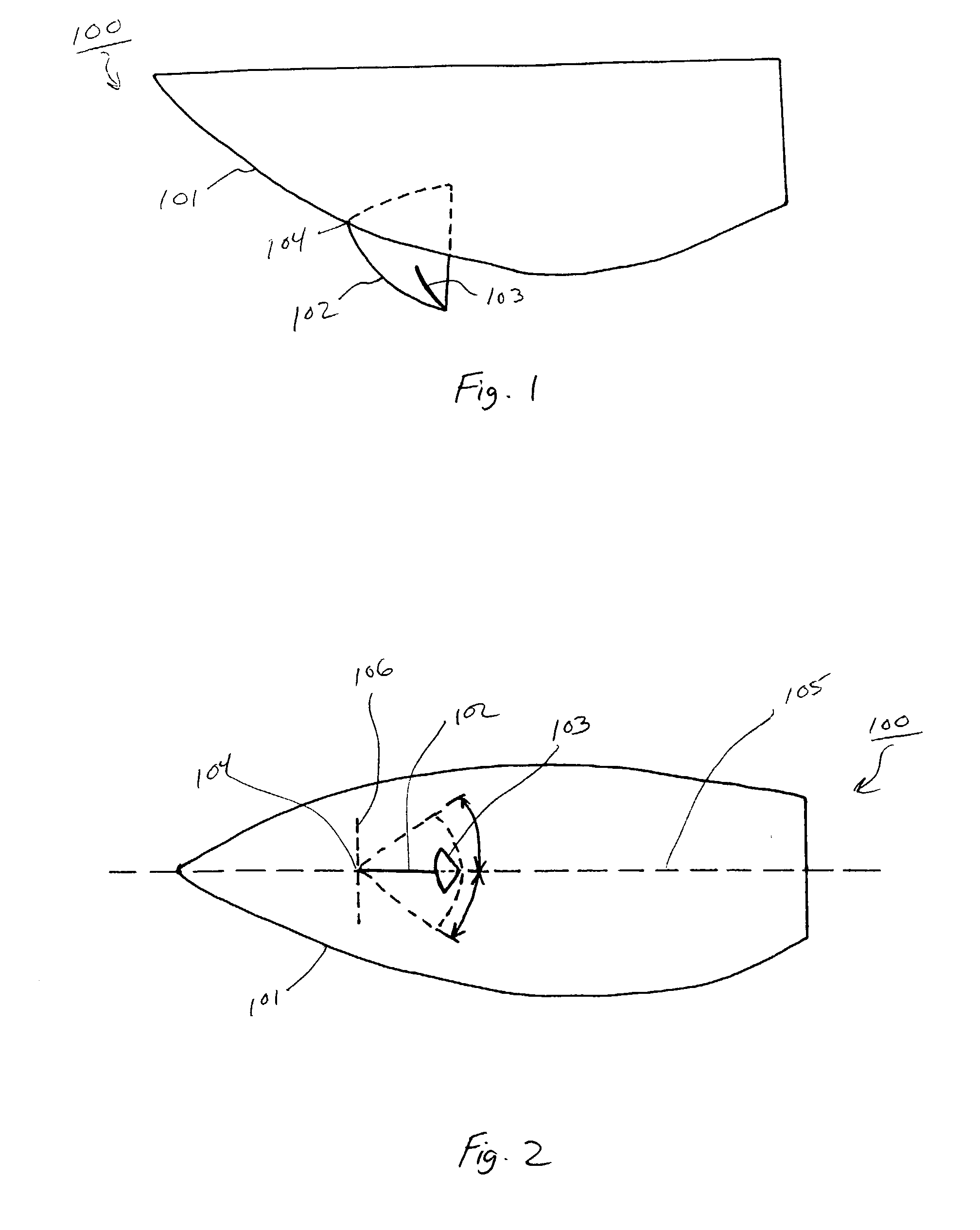
[0063] Referring to FIGS. 1 and 2, a watercraft 100 includes a hull 101. A rudder 102 having an angled flap 103 is deployable under the front and in the middle of the hull 101. As shown in FIG. 2, the rudder 102 is pivotable about a point 104 to allow for steering of the watercraft 100. The rudder 102 is pivotable with respect to the longitudinal axis 105 and a transverse axis 106 of the watercraft 100. The flap 103 is attached to the rudder 102 to provide for braking and lifting of the bow of the watercraft 100.

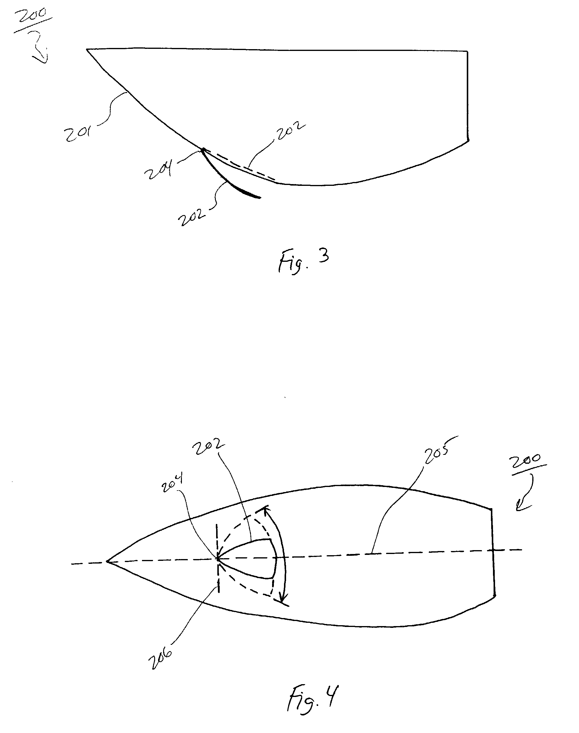
[0064] Referring to...


PUM


Abstract

A watercraft includes a watercraft control mechanism that is capable of steering, decelerating, and / or trimming a watercraft without causing the stern to elevate and the bow to dive; steers or assists steering in off-power situations; steers, trims and / or decelerates a watercraft, or assists in steering, trimming, and / or decelerating a watercraft that can be stowed or retracted to minimize hydrodynamic drag at high speeds; steers, trims and / or decelerates a watercraft, or assists in steering, trimming, and / or decelerating a watercraft that does not become clogged or jammed by seaweed or flotsam or foreign objects floating in the water; and decelerates or assists in decelerating a watercraft in a smooth and stable manner when the watercraft is travelling at high speeds.

Description

[0001] This application claims priority to U.S. Application No. 60 / 316,269, filed Sep. 4, 2001, the entire contents of which are hereby incorporated by reference. U.S. Pat. No. 6,174,210 is hereby incorporated by reference in its entirety.[0002] 1. Field of the Invention[0003] This present invention relates to watercraft control mechanism, and more particularly to watercraft control mechanism that provide enhanced, integrated steering, decelerating and trimming.[0004] 2. Description of Related Art[0005] In recent years, the demands of racers and recreational users alike for greater performance and maneuverability have driven the designers of watercraft to reconsider the control mechanisms used for steering, decelerating and trimming. Various mechanisms are known for steering, decelerating and trimming watercraft and the mechanisms may used alone or in combination.[0006] A watercraft may be steered by either turning the propulsion source, such as an outboard motor or a jet-propulsion...

Claims


Application Information

Patent Timeline
IPC IPC(8): B63B35/73B63H11/11B63H11/113B63H11/117B63H25/38B63H25/44
CPCB63B35/731B63H11/11B63H11/113B63H2025/384B63H25/38B63H25/44B63H2025/063B63H11/117
Inventor SIMARD, RICHARDBEAUREGARD, NORMANDBERTHIAUME, YVESBOURRET, ROBERTDAUNAIS, JEANNADEAU, DANIELPELLETIER, MARTINPESANT, GILLESSPADE, SAMTALBOT, MARTIN
Owner BOMBARDIER RECREATIONAL PROD INC
Learn More