
Power generation plant with compressed air energy system

a power generation plant and energy storage technology, which is applied in the direction of hot gas positive displacement engine plants, jet propulsion plants, machines/engines, etc., can solve the problems of shortening the possible plant operation time, storing air mass, and power loss that could have been generated by the plant, so as to increase the efficiency of the power generation plant and avoid power loss

Inactive Publication Date: 2003-07-17
GENERAL ELECTRIC TECH GMBH
View PDF0 Cites 110 Cited by
  • Summary
  • Abstract
  • Description
  • Claims
  • Application Information

AI Technical Summary

Benefits of technology

[0007] In view of the described background art, it is an object of the invention to provide a power generation plant having a compressed air energy storage system with a means to reduce the pressure of air extracted from a compressed air storage cavern with varying pressure for the use in a turbine or turbine train. In particular, the pressure of the extracted air must be reduced to a level suitable for the operation of a combustion turbine. In view of the background cited, the means for pressure reduction should avoid power losses and provide an increased efficiency of the power generation plant as a whole.
[0008] A power generation plant comprises a compressed air energy system with a cavern for the storage of compressed air, at least one combustion turbine or a turbine train with at least one air turbine and at least one combustion turbine, which drive a generator on a rotor shaft, and means to reduce the pressure of the air that is extracted from the storage cavern for the use in the turbine train or combustion turbine.
[0010] The means for pressure reduction by an expansion turbine enables primarily a pressure reduction of the size necessary (from a range from 100 bars to 60 bars down to about 20 bars) in a power plant with a CAES system or a standard turbine operated with supplemental compressed air stored in a cavern. The power generation plant with this type of pressure reduction has the advantage over plants of the state of the art in that it avoids the energy losses caused by conventional throttling valves. Instead, the energy, which otherwise is lost in the process of pressure reduction, directly drives the generator. Furthermore, the pressure reduction system according to the invention allows the storage of the same mass of air at a same pressure as in systems of the state of the art. This in turn allows an operation of the power generation plant using compressed air from the cavern over a period of time that is not limited by a reduction of mass or pressure of the cavern air. Furthermore, a cavern of same size may be used.

Problems solved by technology

The operation of this CAES system for power generation entails energy losses, which result in a loss in power that could have been generated by the plant.
However, a decrease in stored air mass would result in a shortening of the possible plant operation time using the stored air to supplement the air provided by the compressor for the combustion turbine.
Furthermore, an increase in the cavern volume is rarely an economically feasible solution.
The throttling, however, causes an overall power loss in the power generation system.
Again however, neither of these methods is an economically feasible solution.
Hence, pressure reduction schemes found in standard steam and combustion turbine systems are not readily applicable to a power generation plant with compressed air storage or supplemental air as discussed in this background art.

Method used


Image

  • Power generation plant with compressed air energy system
  • Power generation plant with compressed air energy system
  • Power generation plant with compressed air energy system

Examples


Embodiment Construction

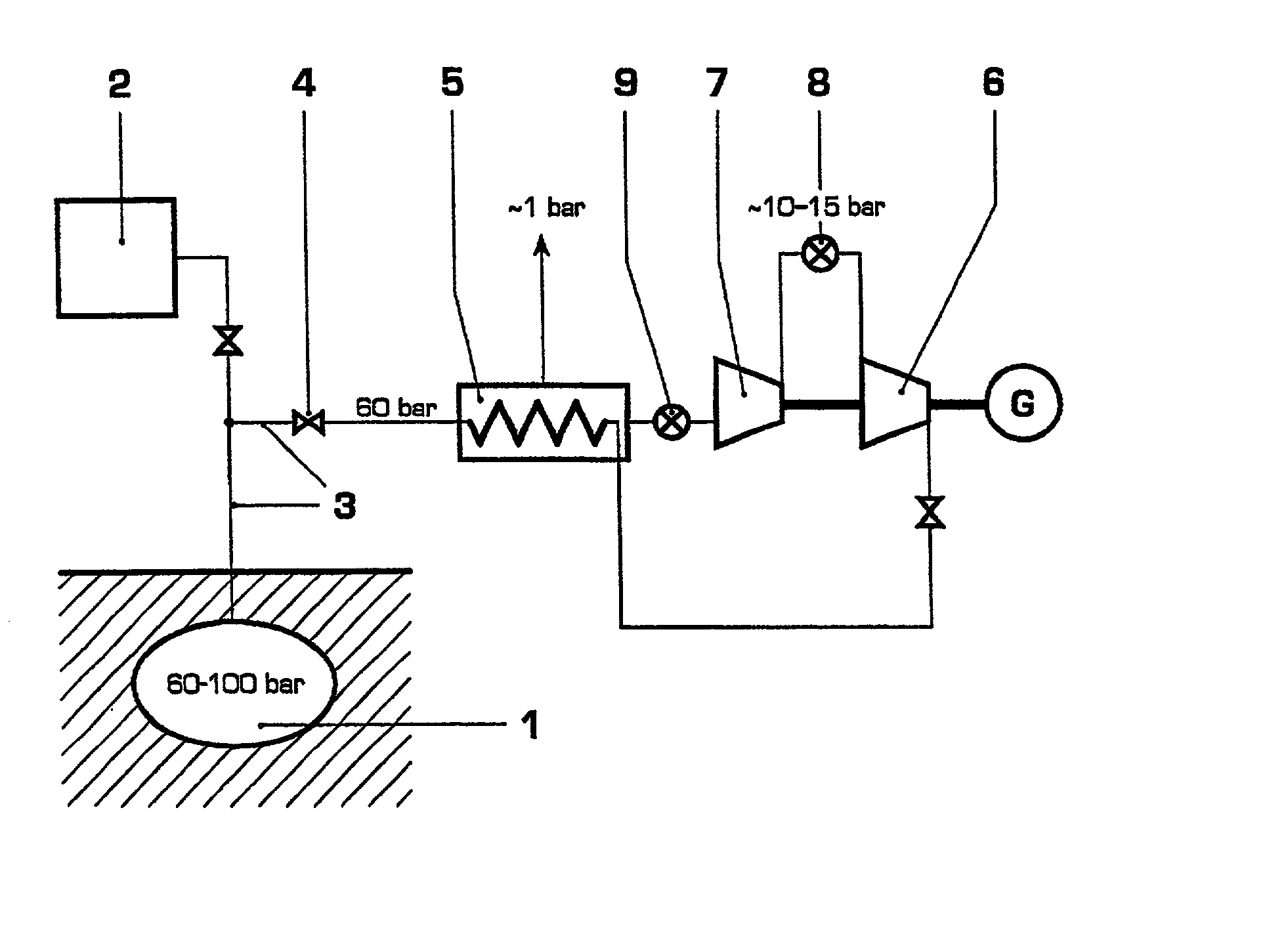
[0031] FIG. 1 is described above in connection with the background art.

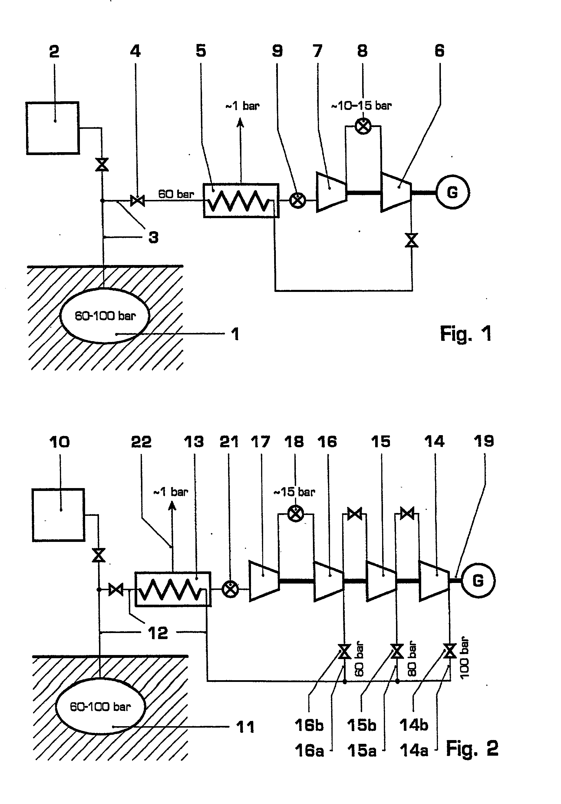
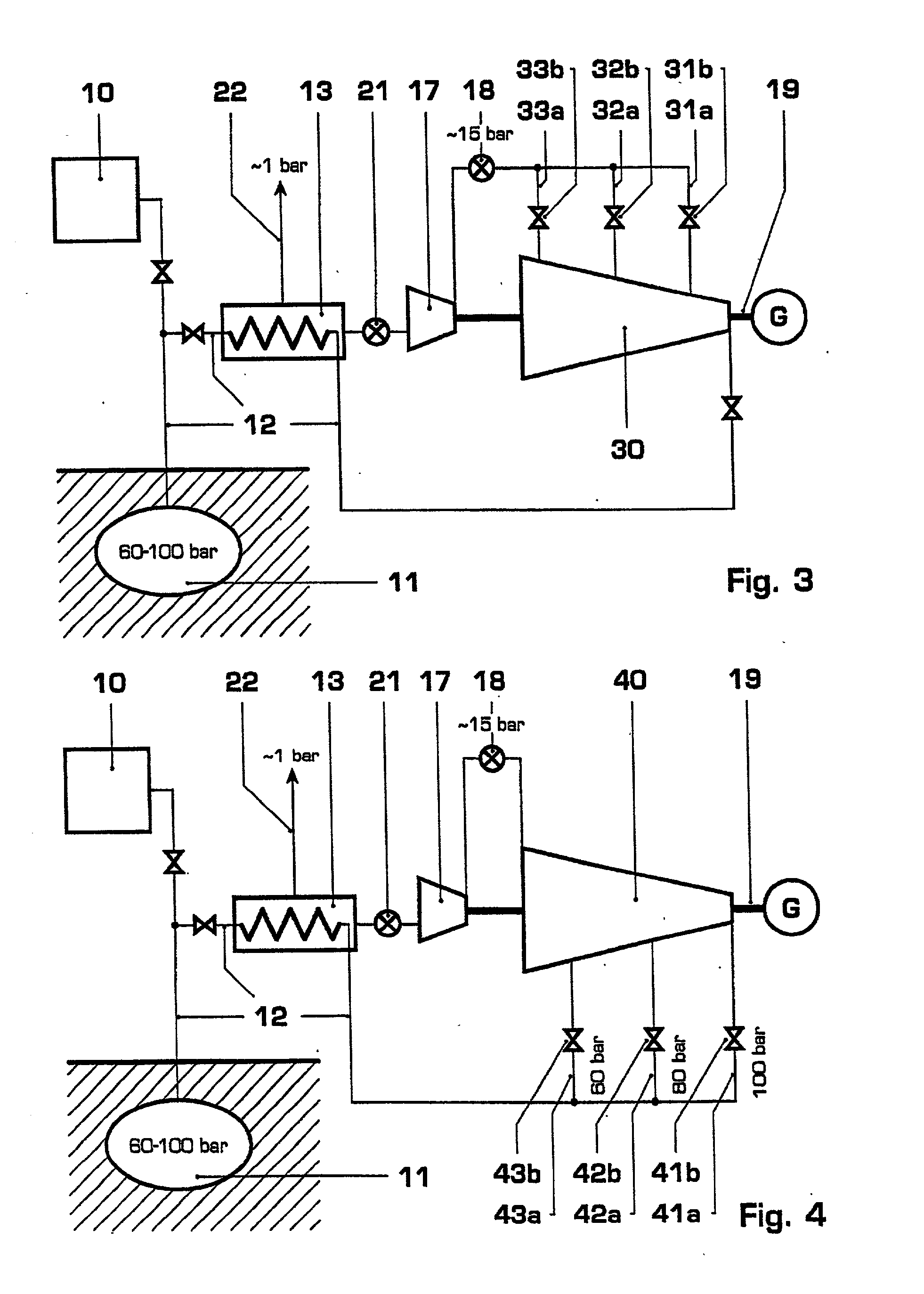
[0032] FIG. 2 shows a power generation plant with a CAES system comprising a compressor train 10 that compresses air to a pressure of about 60 to 100 bar for storage in a cavern 11. During times of high demand for electric power, air is extracted from the cavern 11 via the feed line 12 and directed through a recuperator or preheater 13. After the recuperator, the feed line 13 continues to a turbine train comprising three expansion air turbines 14, 15, 16 and a gas turbine 1. A combustor 18 is arranged in the line connecting the last air expansion turbine 16 and the gas turbine 17. All turbines are arranged on a rotor shaft 19 that drives a generator G. Each expansion air turbine has an inlet line 14a, 15a, 16a with a valve 14b, 15b, 16b. This valve is in the simplest case a stop valve. Preferably however, it is a control or a valve that combines both the function of a stop and that of a control valve. The valves ...


PUM


Abstract

A power generation plant with a compressed air energy storage system comprises a means to reduce the pressure of air extracted from a compressed air storage cavern for the use in a combustion turbine. The means to reduce the air pressure comprises at least one expansion turbine and means to control the size of pressure reduction. Furthermore, the expansion turbine is arranged on a rotor shaft that drives a generator. The means for pressure redact, according to the invention, avoid power losses and provide an increased overall efficiency of the power generation plant.

Description

[0001] The invention pertains to a power generation plant comprising a combustion turbine and a compressed air energy system (CAES) with an air storage cavern and in particular to a means for the reduction of the pressure of air extracted from the storage cavern.[0002] A typical power generation plant with a compressed air energy storage (CAES) system and a combustion as well as an air turbine is shown in FIG. 1. The CAES system comprises a cavern 1 underground, which stores air compressed by a compressor train 2 to a pressure of about 60 to 100 bar. A feed line 3 leads from the cavern 1 to a throttling valve 4, which reduces the air pressure to about 60 bar. The feed line 2 then leads to a heat exchanger or recuperator 5, where the air is preheated, and continues to a turbine train comprising an air turbine 6, a standard gas turbine 7, and a generator G. The air expands in the expansion air turbine 6 and exits through the turbine outlet at a pressure of approximately 15 bar. It the...

Claims


Application Information

Patent Timeline
Patent Type & Authority Applications(United States)
IPC IPC(8): F02C6/16F02C9/16
CPCF02C6/16Y02E60/15F02C9/16Y02E60/16
Inventor GERDES, RALF
Owner GENERAL ELECTRIC TECH GMBH
Learn More