Process and apparatus of combustion for reduction of nitrogen oxide emissions

a technology of nitrogen oxide and process, which is applied in the direction of indirect carbon-dioxide mitigation, air/fuel supply for combustion, lighting and heating apparatus, etc., can solve the problems of low excess air reducing the available oxygen, scr and sncr systems tend to have extremely high capital and maintenance costs,

Inactive Publication Date: 2003-07-17
MARIN OVIDIU +3
View PDF6 Cites 106 Cited by
  • Summary
  • Abstract
  • Description
  • Claims
  • Application Information

AI Technical Summary

Problems solved by technology

Because of the competition, operators of such processes are thus facing a difficult challenge: to increase their productivity under the more and more stringent constraints of higher efficiency and reduced NOx emissions.
Low excess air reduces the available oxygen to the point which is just sufficient to oxidize the fuel but not so much as to cause emis

Method used


Image

  • Process and apparatus of combustion for reduction of nitrogen oxide emissions
  • Process and apparatus of combustion for reduction of nitrogen oxide emissions
  • Process and apparatus of combustion for reduction of nitrogen oxide emissions

Examples


Embodiment Construction

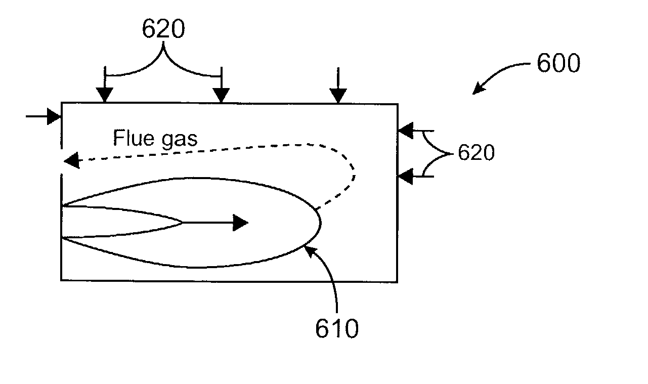
[0081] FIG. 6 illustrates schematically the implementation of a process for fuel combustion in a single burner end fired furnace 600. The oscillating flame 610 is illustrated with the low and high flames represented. The post combustion oxidant is injected at a one or more locations represented by the arrows 620. The post combustion oxidant injection locations are selected to be where the injected oxidant will not interact with the oscillating combustion and where the flue gas temperature is the lowest in the furnace. These locations in the furnace are generally along the back wall and along the exhaust gas path on the side of the furnace. The furnace 600 of FIG. 6 may be any known end fired furnace, such as a glass furnace or steel making furnace.

[0082] FIG. 7 illustrates schematically the implementation of a process for fuel combustion in a multiple burner, cross fired furnace 700. The plurality of oscillating flames 710 are illustrated on both sides of the furnace with the low fl...


PUM


Abstract

A combustion control system allows the dramatic reduction of NOx emission levels from industrial combustion processes without having recourse to expensive flue gas clean up methods. The system combines the technique of oscillating combustion with an adapted system for post combustion burn out of the excess of CO resulting from the low-NOx combustion zone. A process for fuel combustion includes generating an oscillating combustion zone by oscillating at least one of the fuel flow and the oxidant flow to achieve a reduced nitrogen oxide emission, selecting oscillating parameters and furnace operating parameters to maximize nitrogen oxide reduction efficiency to the detriment of carbon monoxide production, and combusting carbon monoxide downstream of the oscillating combustion zone by injecting a post combustion oxidant.

Description

[0001] This application claims priority to U.S. Provisional Application No. 60 / 348,661 filed Jan. 14, 2002, which is incorporated herein by reference in its entirety.[0002] The invention relates to a method and apparatus to reduce nitrogen oxide emissions from industrial combustion processes, and more particularly the invention relates to a method and apparatus to reduce nitrogen oxide emissions without affecting other emissions, such as carbon monoxide, by combining the technique of oscillating combustion with a system of post combustion removal of carbon monoxide.DESCRIPTION OF THE RELATED ART[0003] High-temperature, gas-fired furnaces, especially those fired with preheated air or industrial oxygen, produce significant quantities of nitrogen oxides (NOx) per unit of material processed. At the same time, regulations on emissions from industrial furnaces are becoming increasingly more stringent, especially in areas such as California.[0004] Operators have been looking for improved c...

Claims


Application Information

Patent Timeline
IPC IPC(8): F23C6/04F23C7/00F23C99/00F23L7/00
CPCF23C6/045F23C7/00F23C99/00Y02E20/344F23K2900/05003F23L7/007F23L2900/07005F23C2900/06041Y02E20/34
Inventor MARIN, OVIDIUPENFORNIS, ERWINBOURHIS, YVESBUGEAT, BENJAMIN
Owner MARIN OVIDIU
Why Eureka
Try Eureka