Drive method of an electro-optical device, a drive circuit and an electro-optical device and electronic apparatus

a drive circuit and electro-optical technology, applied in the direction of static indicating devices, instruments, television systems, etc., can solve the problems of high cost of the overall apparatus, difficult to maintain high quality displaying, and serious problems

Active Publication Date: 2003-07-24
BOE TECH GRP CO LTD
View PDF8 Cites 63 Cited by
  • Summary
  • Abstract
  • Description
  • Claims
  • Application Information

AI Technical Summary

Problems solved by technology

Hence, an overall apparatus is highly expensive since an analog circuit or an operational amplifier is necessary for a peripheral circuitry of an electro-optical device.
In addition, non-uniformity on display quality occurs due to characteristics of these analog circuit and operational amplifier and / or irregularity of wiring resistance so that it is difficult to maintain high quality displaying.
Especially, these problems become serious in case of displaying a fine and accurate image.

Method used


Image

  • Drive method of an electro-optical device, a drive circuit and an electro-optical device and electronic apparatus
  • Drive method of an electro-optical device, a drive circuit and an electro-optical device and electronic apparatus
  • Drive method of an electro-optical device, a drive circuit and an electro-optical device and electronic apparatus

Examples


Embodiment Construction

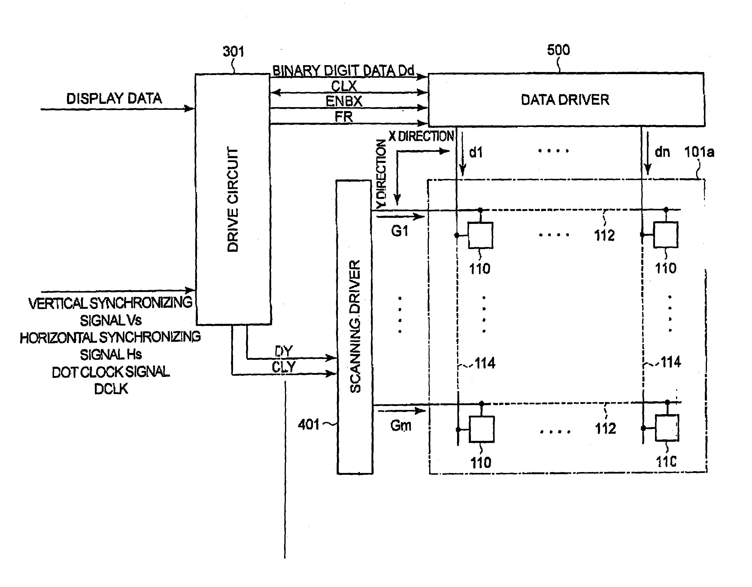
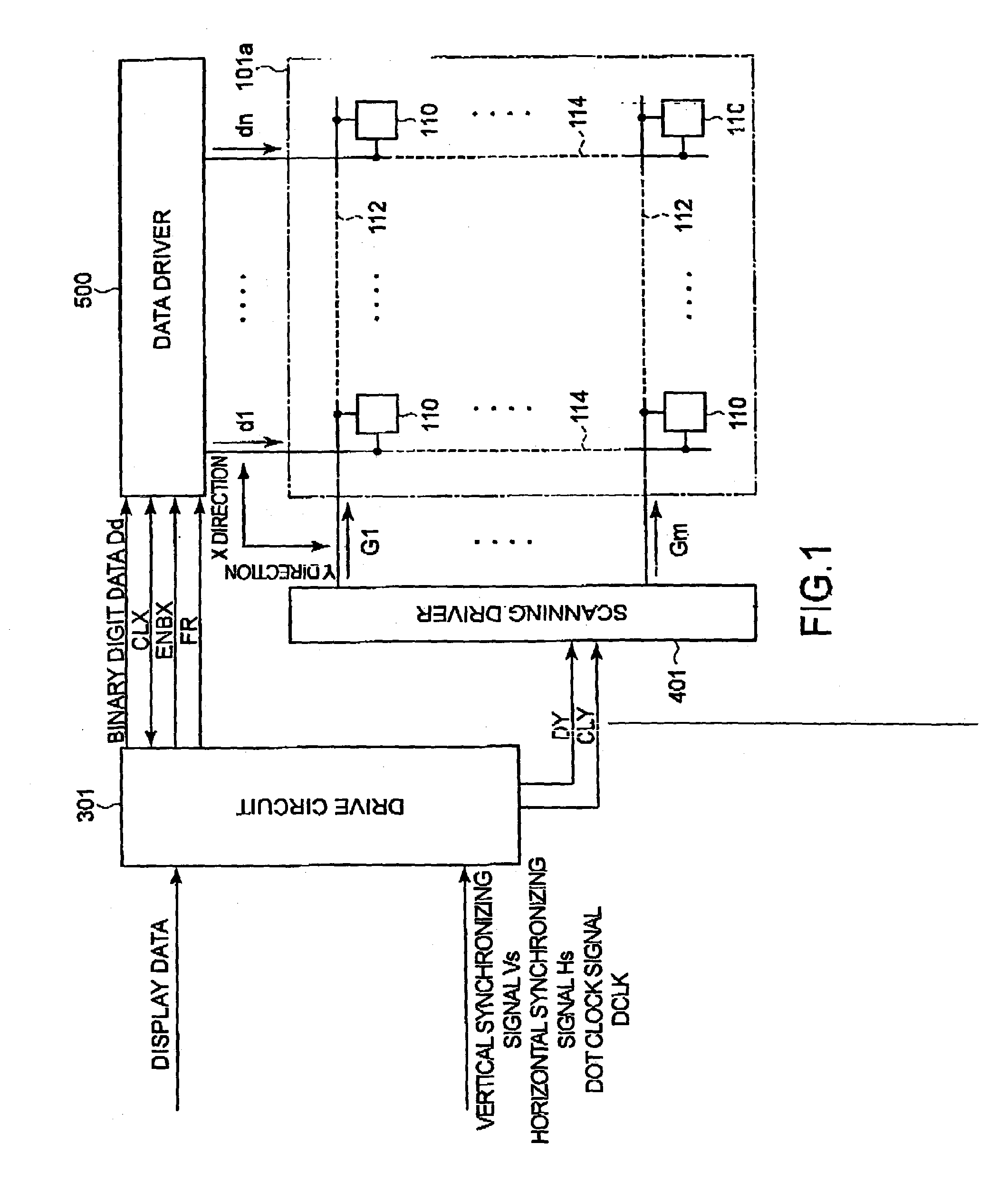
[0048] The preferred embodiment of the present invention is hereinafter explained in detail with reference to drawings. FIG. 1 is a block diagram showing an electro-optical device related to the first embodiment of the present invention.

[0049] An electro-optical device related to the present embodiment is a liquid crystal device, in which liquid crystal is used as electro-optical material, for example, it includes a structure where an element substrate and an opposite substrate are affixed together keeping a specific spacing as described hereinafter and liquid crystal as electro-optical material is sandwiched within this spacing. Here, a display mode of the electro-optical device is normally black, namely a white image is displayed when voltage is applied to a pixel (on-state) and a black image is displayed when voltage is not applied (off-state).

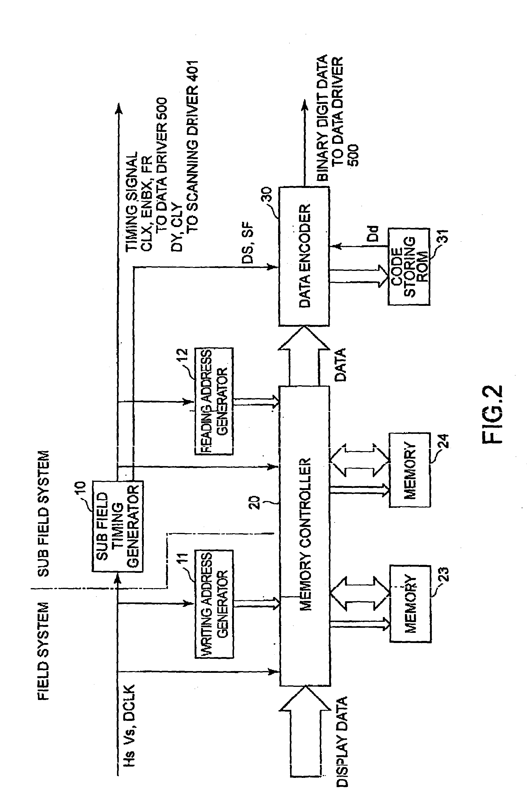
[0050] According to the present embodiment, a sub field drive method is adopted as a method of driving liquid crystal, where 1 field is di...


PUM

PropertyMeasurementUnit
timeaaaaaaaaaa
degree of freedomaaaaaaaaaa
light transmittanceaaaaaaaaaa

Abstract

1 field is divided into plural sub fields on a time axis, each of which is a control unit to drive a pixel. A code storing ROM 31 stores a code to give an sub field drive pattern based on display data. With respect to adjacent pixels within a control area, a data encoder 30 writes pixel data by using a sub field drive pattern read from the code storing ROM 31 and a pattern delayed by the predetermined sub field period. Hence, adjacent pixels are driven by different sub fields drive patterns each other so that timing of flickering among adjacent pixels is differentiated. Thus, flickering can be reduced.

Description

[0001] 1. Technical Field of the Invention[0002] The present invention relates to a method of driving an electro-optical device where gray-scale display is controlled by a sub field-drive method, a drive circuit and an electronic apparatus thereof.[0003] 2. Prior Art[0004] An electro-optical device such as a liquid crystal display using liquid crystal as electro-optical material, for example, is widely unitized for a display portion of various kinds of information apparatus and a liquid crystal TV and so on as a display device that can replace a cathode ray tube (CRT).[0005] Such liquid crystal display device, for example, comprises pixel electrodes arranged in a matrix, an element substrate including switching elements such as TFT (Thin Film Transistor) connected to these pixel electrodes, an opposite substrate including an electrode opposite to each of the pixel electrodes and liquid crystal as electro-optical material filled between these substrates.[0006] A display mode of such ...

Claims


Application Information

Patent Timeline
Patent Type & Authority Applications(United States)
IPC IPC(8): G09G3/20G02F1/133G09G3/36H04N5/66
CPCG09G3/20G09G3/2022G09G2320/0247G09G3/28G09G3/3611G09G3/2025
Inventor IISAKA, HIDEHITO
Owner BOE TECH GRP CO LTD
Why Eureka
Try Eureka