Moving blade for a high pressure turbine, the blade having a trailing edge of improved thermal behavior

Inactive Publication Date: 2003-07-24
SNECMA MOTEURS SA
View PDF6 Cites 22 Cited by
  • Summary
  • Abstract
  • Description
  • Claims
  • Application Information

AI Technical Summary

Benefits of technology

0006] The present invention thus seeks to mitigate that drawback by proposing a moving blade for a high pressure turbine that presents a novel shape that avoids cracking. The invention also seeks to avoid degrading the general mechanical strength of the

Problems solved by technology

These temperatures reach values that are well above those that can be withstood without damage by the blades which are in contact with said gases, and as a result their lifetime is limited.
Unfortunately, in practice, the connection zone situated between the slot and the platform supporting the blade is very poorly cooled, particularly since the air exhausted via the slot tends

Method used


Image

  • Moving blade for a high pressure turbine, the blade having a trailing edge of improved thermal behavior
  • Moving blade for a high pressure turbine, the blade having a trailing edge of improved thermal behavior
  • Moving blade for a high pressure turbine, the blade having a trailing edge of improved thermal behavior

Examples


Example

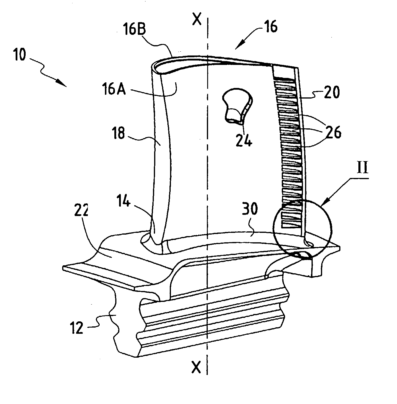
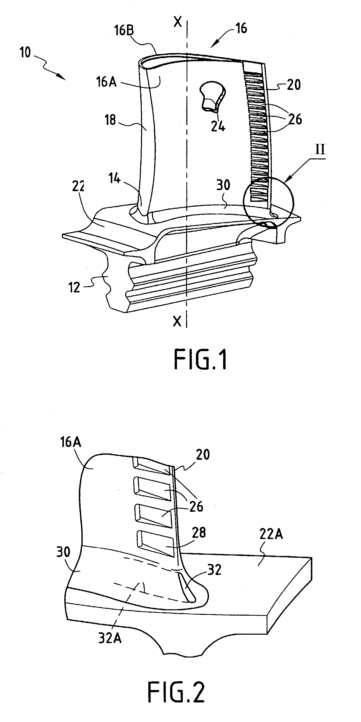
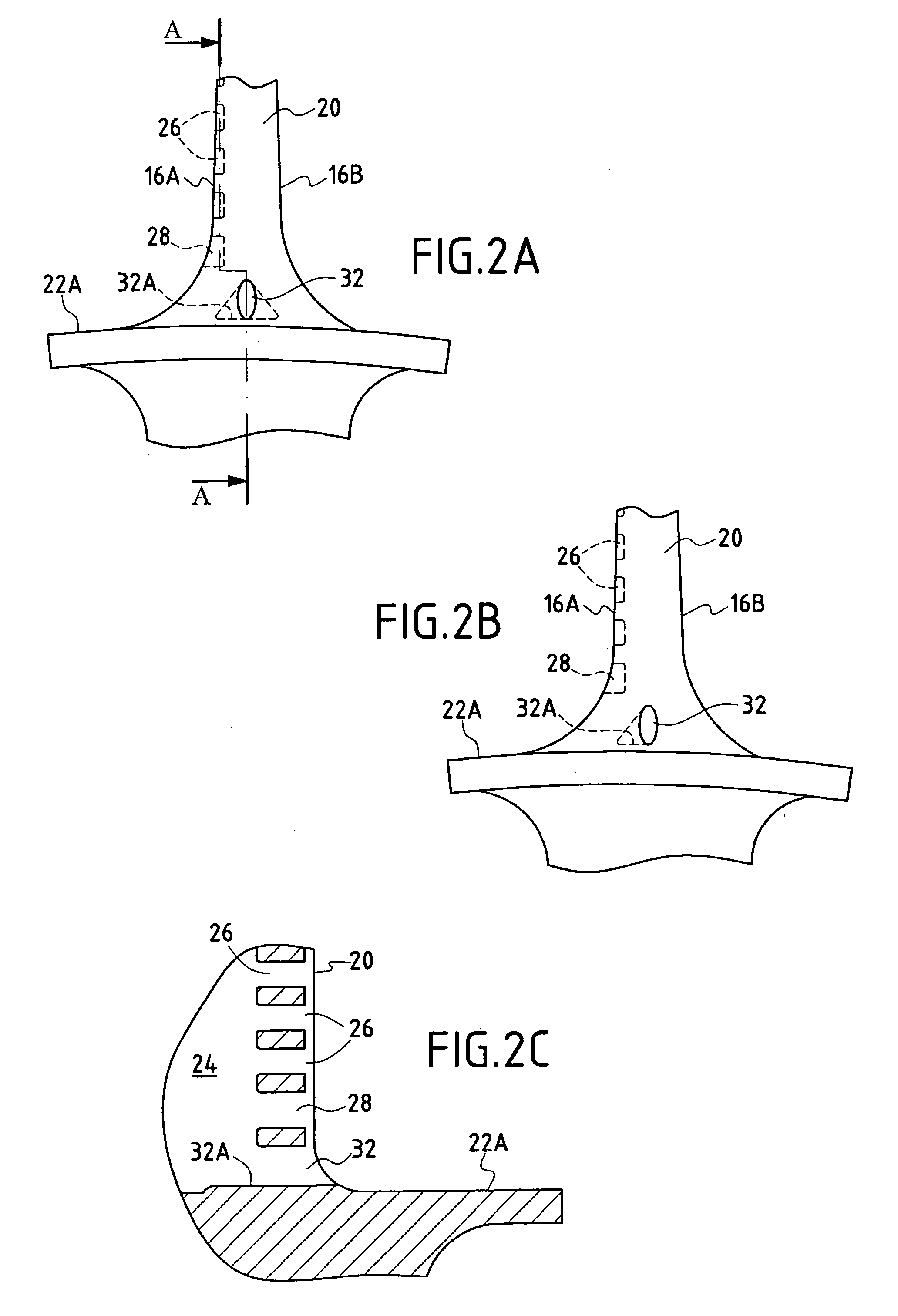
[0019] FIG. 1 is a perspective view of a moving blade 10 in accordance with the present invention, e.g. for a high pressure turbine in a turbomachine. This blade has a longitudinal axis X-X and it is fixed to a rotor disk (not shown) of the high pressure turbine by means of a root 12 that is generally in the shape of a fir-tree. It typically comprises a base 14A, a tip 14B, a concave wall 16A, a convex wall 16B, a leading edge 18, and a trailing edge 20. The root 12 joins the base 14A of the blade at a platform 22 defining an inside wall for the stream of combustion gas flowing through the high pressure turbine.

[0020] Such a blade is subjected to the very high temperatures of the combustion gases and it therefore needs to be cooled. For this purpose, and in known manner, the moving blade 10 has at least one internal cooling circuit made up, for example, of at least one cavity 24 extending radially between the base 14A and the tip 14B of the blade. This cavity is fed with cooling air...


PUM


Abstract

A moving blade for a high pressure turbine of a turbomachine, the blade having at least one cooling circuit comprising at least one cavity extending radially between a tip and a base of the blade, at least one air admission opening at a radial end of the cavity(ies) to feed the cooling circuit(s) with cooing air, and a plurality of slots opening out into the cavity(ies) and opening out into the concave side of the blade between the base and the tip of the blade in a manner that is substantially perpendicular to a longitudinal axis of the blade, a connection zone being provided between a slot closest to the base of the blade and a top surface of a platform defining an inside wall for a stream of combustion gas flowing through the high pressure turbine, and the moving blade further comprising an additional cooling air exhaust slot opening out into said cavity and opening out into said connection zone in line with the trailing edge.

Description

[0001] The present invention relates to the general field of moving blades for a high pressure turbine in a turbomachine, and more particularly it relates to slots for exhausting cooling air from the moving blades of a high pressure turbine.[0002] In conventional manner, a turbomachine has a combustion chamber in which air and fuel are mixed together prior to being burned therein. The gas that results from this combustion flows downstream in the combustion chamber and then feeds a high pressure turbine. The high pressure turbine has one or more rows of moving blades that are circumferentially spaced apart all around the rotor of the turbine. The moving blades of the high pressure turbine are thus subjected to the very high temperatures of the combustion gases. These temperatures reach values that are well above those that can be withstood without damage by the blades which are in contact with said gases, and as a result their lifetime is limited.[0003] In order to solve this problem...

Claims


Application Information

Patent Timeline
IPC IPC(8): F01D5/18
CPCF01D5/186F05B2240/801F01D5/187F05D2240/81
Inventor BOURY, JACQUESJUDET, MAURICETABARDIN, JACKY
Owner SNECMA MOTEURS SA
Why Eureka
Try Eureka