Door glass raising and falling apparatus

a technology for raising and falling door glass, which is applied in the directions of doors, wing accessories, transportation and packaging, etc., can solve the problems of excessive stress on the door glass, the door glass cannot be raised and fallen smoothly, and the time and labor required to assemble the front and rear carrier plates

Inactive Publication Date: 2003-08-28
ANSEI CORP
View PDF0 Cites 5 Cited by
  • Summary
  • Abstract
  • Description
  • Claims
  • Application Information

AI Technical Summary

Problems solved by technology

To assemble the door glass to the front and rear carrier plates in such unstable state, an operator must match the position and attitude of one carrier plate to the door glass before the one carrier plate is assembled to the door glass and, after then, the other carrier plate must be assembled to the door glass similarly, with the result that it takes time and labor to assemble the door glass to the front and rear carrier plates.
On the other hand, in the door glass raising and falling apparatus according to the related art 2, when the door glass rises and falls along the vertically extending guide members, the front and rear end edges of the door glass move in the vertical

Method used


Image

  • Door glass raising and falling apparatus
  • Door glass raising and falling apparatus
  • Door glass raising and falling apparatus

Examples


first embodiment

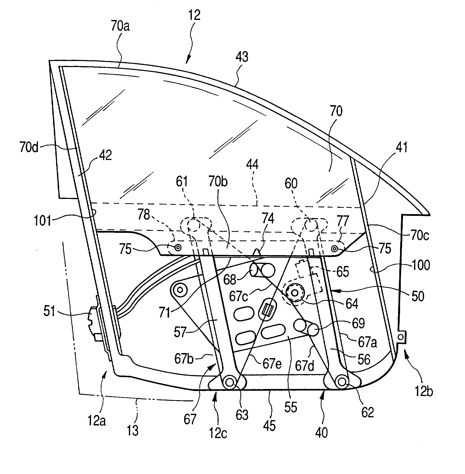
[0023] Now, description will be given below of a vehicle door including a door glass raising and falling apparatus according to the invention with reference to FIGS. 1 to 7.

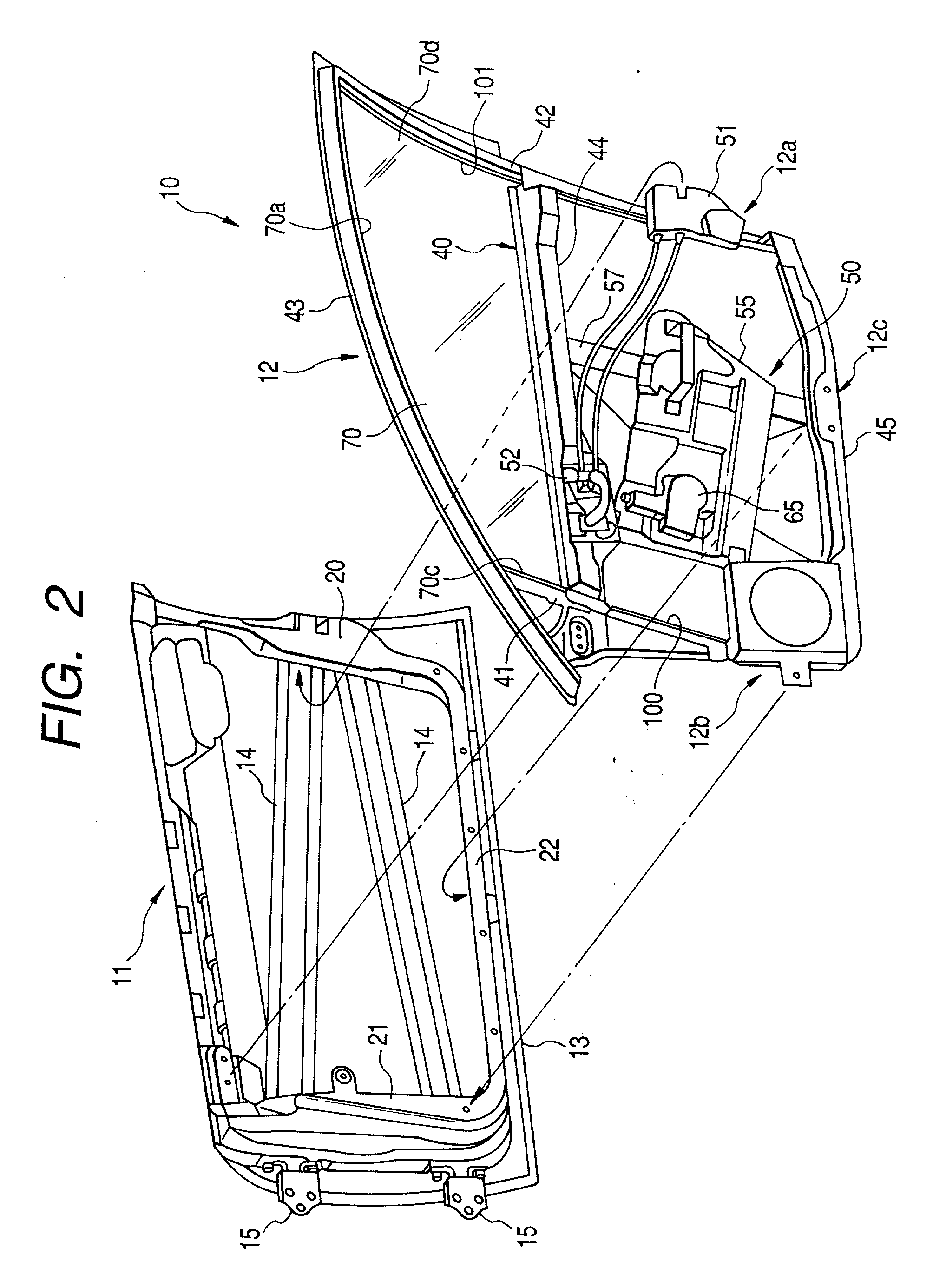
[0024] A car door 10 shown in FIG. 2 comprises a door panel unit 11 and a door module 12. The door panel unit 11 includes an outer panel 13 forming the outer wall surface of the door 10, reinforcing members 14 respectively provided on the inside of the vehicle for reinforcement of the outer panel 13, hinge members 15 respectively used to mount the door 10 onto a vehicle body, and inner panels 20, 21, 22 respectively provided on the peripheral edge portion (which is situated on the inside of the vehicle) of the outer panel 13.

[0025] On the other hand, the door module 12, as shown in FIG. 1, comprises a frame structure 40 which constitutes the skeleton of the door module 12. Since FIG. 1 is a side view of the door module 12 when it is viewed from outside the vehicle, in FIG. 1, the right and left position relation ...


PUM


Abstract

The door glass raising and falling apparatus comprises a carrier plate 71 to be mounted onto the lower end portion 70b of a door glass 70. The door glass 70 is capable of rising and falling along sashes 41, 42 respectively disposed in the front and rear portions of a door. The carrier plate 71 extends in the back-and-forth direction of the door glass 70 along the lower end of the door glass 70 and includes securing portions respectively formed in the given portions of the carrier plate 71, while the moving portions 67a, 67b of a wire-rope body 67 can be respectively fixed to the securing portions of the carrier plate 71. The carrier plate 71 further comprises a glass support portion 74 for supporting the middle portion of the lower end of the door glass 70 in the back-and-forth direction thereof, and a pair of front and rear glass fixing portions 77, 78 each including a screw member 75. In the door glass 70, there are formed mounting holes which can be supported by the glass fixing portions 77, 78, respectively. The dimension of each of the mounting holes is set sufficiently larger than the outside diameter of the shaft portion of each of the screw members 75 so that, when the screw members 75 are loosened, the door glass 70 can be moved with respect to the carrier plate 71. Also, the door glass raising and falling apparatus further comprises a wire-rope body 150 for raising and falling a glass rising and falling body 162. The wire-rope body 150 is wired over and between a plurality of pulleys. Of these pulleys, pulleys 142, 143, which are situated on the lower side, are rotatably mounted on frame members 136, 137 by pulley shafts 182 respectively. Rubber stoppers 184 are mounted on the pulley shafts 182, respectively. The rubber stoppers 184 are structured such that, when the glass rising and falling body 162 reaches its falling limit, the lower end face of the glass rising and falling body 162 can be contacted with the rubber stoppers 184.

Description

[0001] 1. Field of the Invention[0002] The present invention relates to a door glass raising and falling apparatus and,. in particular, to a door glass raising and falling apparatus suitable for use in a car.[0003] 2. Description of the Related Art[0004] Conventionally, in a vehicle such as a car, various kinds of door glass raising and falling apparatus for raising and falling a door glass have been proposed and put to practical use.[0005] For example, in JP-A-10-102902 (Related art 1), there is disclosed a structure in which a door glass is slidably supported by front and rear sashes, carrier plates are secured to a pair of front and rear wire-rope moving portions, and the front and rear portions of the door glass are supported by the carrier plates.[0006] Also, in JP-A-11-44151 (Related art 2), there is disclosed a structure in which the front and rear portions of a door glass are respectively supported by a pair of front and rear glass support members which are respectively secu...

Claims


Application Information

Patent Timeline
IPC IPC(8): B60J1/17B60J3/02E05F11/38E05F11/48
CPCB60J1/17E05F11/385E05F11/485E05F11/488E05F2011/387E05Y2201/706E05Y2201/654E05Y2201/668E05Y2600/10E05Y2600/60E05Y2900/55E05Y2201/64B60J3/02
Inventor SAKAGUCHI, MASATOSHIUCHIKATA, TOSHIAKIISHII, KOJI
Owner ANSEI CORP
Why Eureka
Try Eureka