Method and apparatus for minimizing adverse effects of thermal expansion in a heat exchange reactor
a technology of heat exchange reactor and thermal expansion, which is applied in the direction of lighting and heating apparatus, gas-gas reaction process, laminated elements, etc., can solve the problems of thermal stress, particularly challenging thermal stress, and formidable challenges in the provision of features in tubular array heat exchange reactors
Inactive Publication Date: 2003-09-18
LAIR LIQUIDE SA POUR LETUDE & LEXPLOITATION DES PROCEDES GEORGES CLAUDE
View PDF10 Cites 49 Cited by
- Summary
- Abstract
- Description
- Claims
- Application Information
AI Technical Summary
Benefits of technology
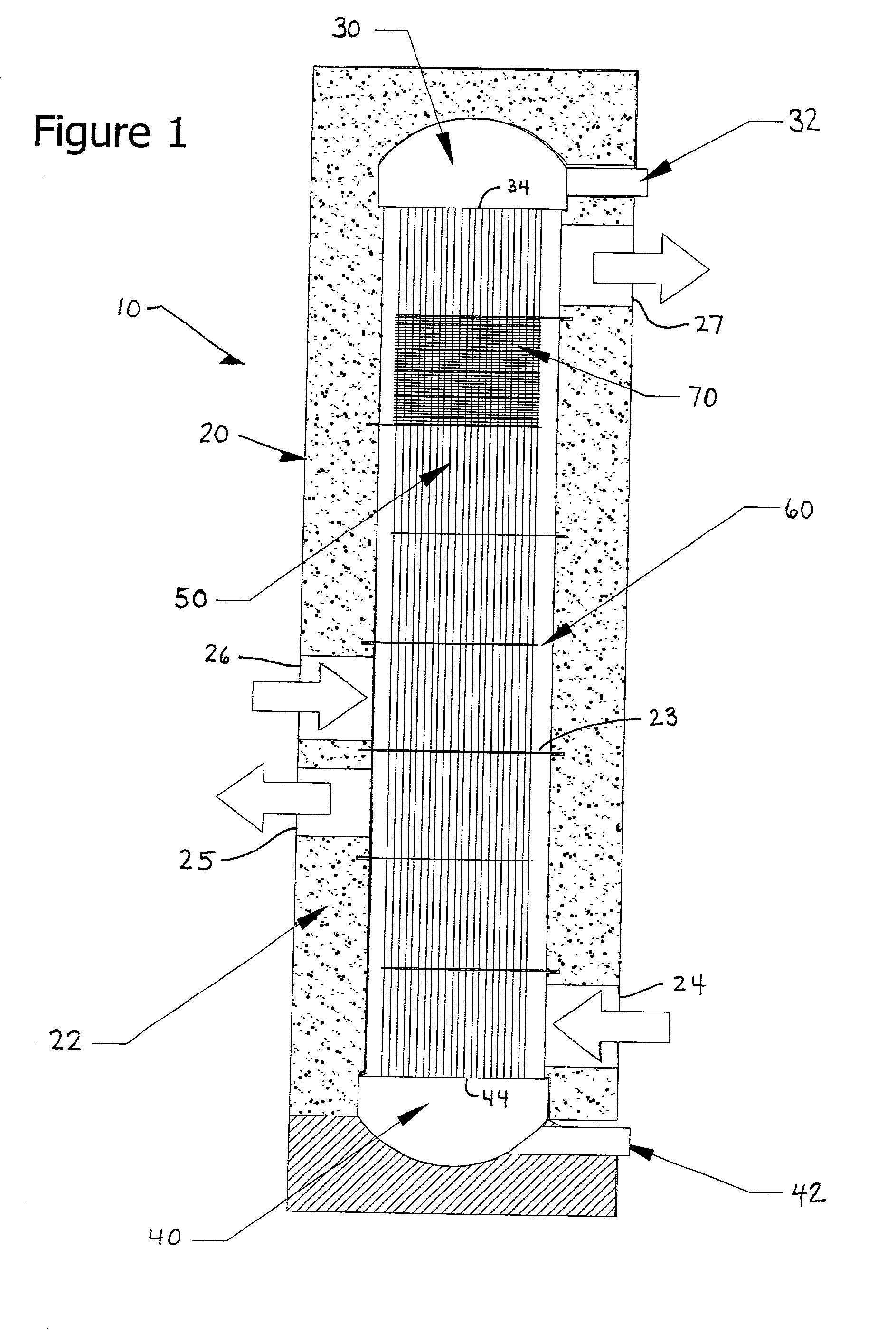
[0012] The present invention advantageously provides a heat exchange reactor including a housing, a plurality of tubes mounted in the housing and configured to carry a first fluid, and a baffle having a plurality of holes receiving the tubes. The baffle is configured to guide a second fluid provided within the housing to flow in a direction generally perpendicular to the tubes. The heat exchange reactor further advantageously includes various means for minimizing adverse effects of thermal expansion of at least one of the baffle and the plurality of tubes.
[0013] In an embodiment of the present invention, the heat exchange reactor further includes a first header plate mounting first ends of the tubes within the housing and a second header plate mounting second ends of the tubes within the housing. In this embodiment, the means for minimizing adverse effects of thermal expansion includes means for reducing a differential thermal expansion between the first header plate, the second header plate, and the baffle. For example, the differential thermal expansion can be reduced by selecting materials for these elements that provide similar thermal expansion depending upon a specific temperature zone in which the element is mounted within the housing.
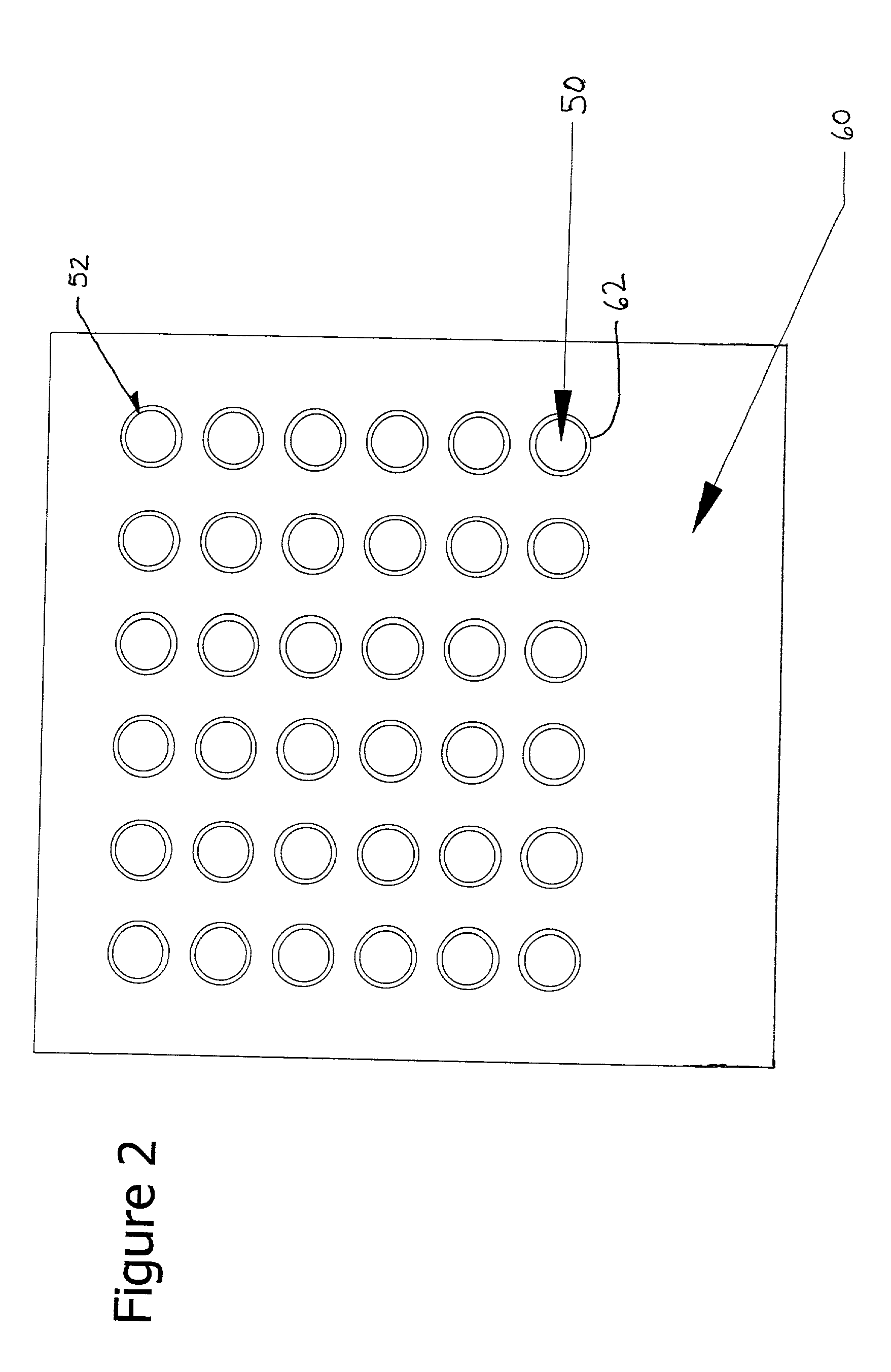
[0014] In another embodiment of the present invention, the heat exchange reactor is configured such that the means for minimizing adverse effects of thermal expansion includes means for minimizing mechanical interference between the baffle and the plurality of tubes in both an operational state of the heat exchange reactor and a non-operational state of the heat exchange reactor. For example, at least one hole of the plurality of holes can be shaped to minimize mechanical interference between a respective tube extending through the at least one hole to minimize mechanical interference between the baffle and the respective tube in both the operational state of the heat exchange reactor and the non-operational state of the heat exchange reactor when the various elements have thermally expanded.
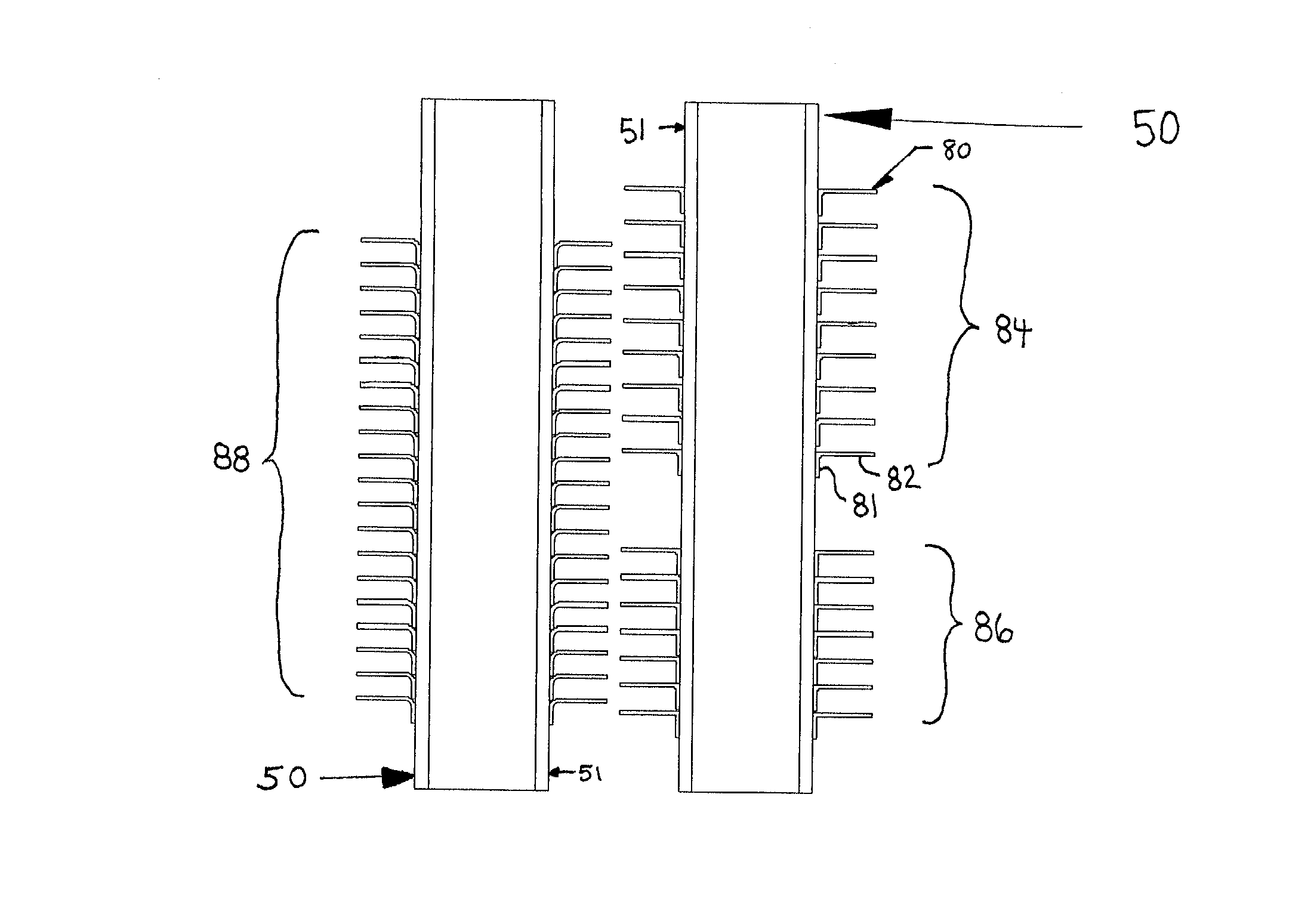
[0015] In a further embodiment of the present invention, the heat exchange reactor is configured such that the means for minimizing the adverse effects of thermal expansion includes means for providing a thermal insulation zone along a length of the tubes at a large temperature gradient zone within the heat exchange reactor.
[0016] In a further embodiment of the present invention, the heat exchange reactor further includes a heat transfer fin in contact with at least one of the tubes, such that the heat transfer fin is configured to contact the second fluid provided within the housing. The heat exchange reactor includes means for minimizing adverse effects of thermal expansion of the heat transfer fin. For example, the heat transfer fin can be in contact with one tube of the plurality of tubes, such that the heat transfer fin is not attached to another tube of the plurality of tubes.
Problems solved by technology
If free expansion is not allowed for in the configuration of the heat exchange reactor, then the unrealized strains result in thermal stresses.
The thermal stresses are particularly challenging in hydrocarbon steam reformers because the temperature gradients are generally very high.
The provision of features in tubular array heat exchange reactors presents formidable challenges due to the thermal gradients along the axis of the tubes.
These forces can cause premature structural failure of the reactor unless exceptionally strong tubes are employed, which is undesirable for several reasons, including an objectionable increase in the material usage in the construction of the reactor, as well as an attendant increase in volume and weight of the reactor.
Furthermore, the local stresses can significantly shorten the useful operating lifetime of the heat exchange reactor 10.
The choice of the smallest diameter hole which completely avoids mechanical interference upon temperature cycling for any given tube is preferred to best control flow bypassing of the baffle, which reduces the heat transfer performance of the heat exchange reactor.
Depending upon the method of manufacture of the baffle, the provision of the non-circular hole may undesirably increase manufacturing expense relative to the methods employing circular holes.
These gradients may cause significant internal stresses in the walls of the tubes 50, which lead to reduced tube life for a given tube thickness.
However, these oversized holes undesirably provide a route for fluid bypass directly from zone 25 to zone 26.
Method used
View moreImage
Smart ImageViewing Examples
Examples
example 2
hole area Percent hole area Percent (sq. in.) open area (sq. in.) open area concentric, round 0.328 40% 0.272 28% non-concentric, round 0.267 26% 0.241 19% non-round 0.256 23% 0.236 17%
[0054] These hole areas and open areas are the worst-case values for the outermost tubes. The sizes of the holes may be reduced for tubes located closer to the center of the tube array according to the teachings of the present invention.
Login to View More PUM
| Property | Measurement | Unit |
|---|---|---|
| Fraction | aaaaa | aaaaa |
| Fraction | aaaaa | aaaaa |
| Fraction | aaaaa | aaaaa |
Abstract
A heat exchange reactor including a housing, a plurality of tubes mounted in the housing and configured to carry a first fluid, and a baffle having a plurality of holes receiving the tubes. The baffle is configured to guide a second fluid provided within the housing to flow in a direction generally perpendicular to the tubes. The reactor includes various configurations for minimizing adverse effects of thermal expansion of the baffle and the tubes. The reactor is configured to minimize mechanical interference between the baffle and the tubes in both an operational state and a non-operational state, for example, by shaping the holes in the baffle to take into account thermal expansion. The reactor also includes a thermal insulator along a length of the tubes at a large temperature gradient zone within the reactor. The reactor further includes a heat transfer fin in contact with only one of the tubes.
Description
[0001] 1. Field of the Invention[0002] The present invention relates to heat exchange reactors and methods of constructing heat exchange reactors.[0003] 2. Discussion of the Background[0004] Heat exchange reactors are often employed to carry out chemical reactions where significant quantities of heat must be added or removed from a first reacting fluid to a second heat transfer fluid, which may or may not be reacting. These heat exchange reactors often bear a strong resemblance to simple heat exchangers, but are often provided with additional features such as fixed beds of catalysts, specialized flowpath designs, exotic materials and the like. Heat exchange reactors are constructed in many forms, including plate-fin and tubular arrays.[0005] An example of a reaction conducted in heat exchange reactors is the steam reformation of hydrocarbon feedstocks to produce hydrogen-containing gas mixtures. In this process, a mixture of steam and hydrocarbon is passed through one fluid circuit ...
Claims
Login to View More Application Information
Patent Timeline
 IPC IPC(8): F28F1/32B01JB01J2/00B01J8/00B01J8/06B01J12/00B01J19/00B01J19/24C01B3/34F28D7/00F28D7/10F28D7/16F28D9/00F28D21/00F28F1/42F28F3/00F28F7/00F28F9/013F28F9/02F28F9/22F28F13/14
CPCB01J8/008F28F2265/26B01J19/0013B01J19/006B01J19/2425B01J2208/00221B01J2208/00495B01J2219/00094B01J2219/00155B01J2219/00777C01B3/34C01B2203/0233C01B2203/0805F28D7/0066F28D7/0091F28D7/1653F28F9/22F28F13/14B01J8/067F28F21/083F28D7/00F28F7/00F28F9/02
Inventor LOMAX, FRANKLIN D. JR.STREEKS, MICHAEL SEANWAIDE, STEPHEN
Owner LAIR LIQUIDE SA POUR LETUDE & LEXPLOITATION DES PROCEDES GEORGES CLAUDE
Features
- R&D
- Intellectual Property
- Life Sciences
- Materials
- Tech Scout
- Unparalleled Data Quality
- Higher Quality Content
- 60% Fewer Hallucinations
Learn More Browse by: Latest US Patents, China's latest patents, Technical Efficacy Thesaurus, Application Domain, Technology Topic, Popular Technical Reports.
© 2025 PatSnap. All rights reserved.Legal|Privacy policy|Modern Slavery Act Transparency Statement|Sitemap|About US| Contact US: help@patsnap.com


