Tree pruner

a tree and pruner technology, applied in the field of tree pruners, can solve the problems of troublesome stowage of the pull cord (64) of the conventional tree pruner, inability to cut off a large diameter tree part, etc., and achieve the effect of increasing the travel of the pull cord and facilitating the cutting off of the tree par

a tree and pruner technology, applied in the field of tree pruners, can solve the problems of troublesome stowage of the pull cord (64) of the conventional tree pruner, inability to cut off a large diameter tree part, etc., and achieve the effect of increasing the travel of the pull cord and facilitating the cutting off of the tree par

US20030177644A1Inactive Publication Date: 2003-09-25CHENG KUN CHIA

Image

  • Tree pruner
  • Tree pruner
  • Tree pruner

Examples


Embodiment Construction

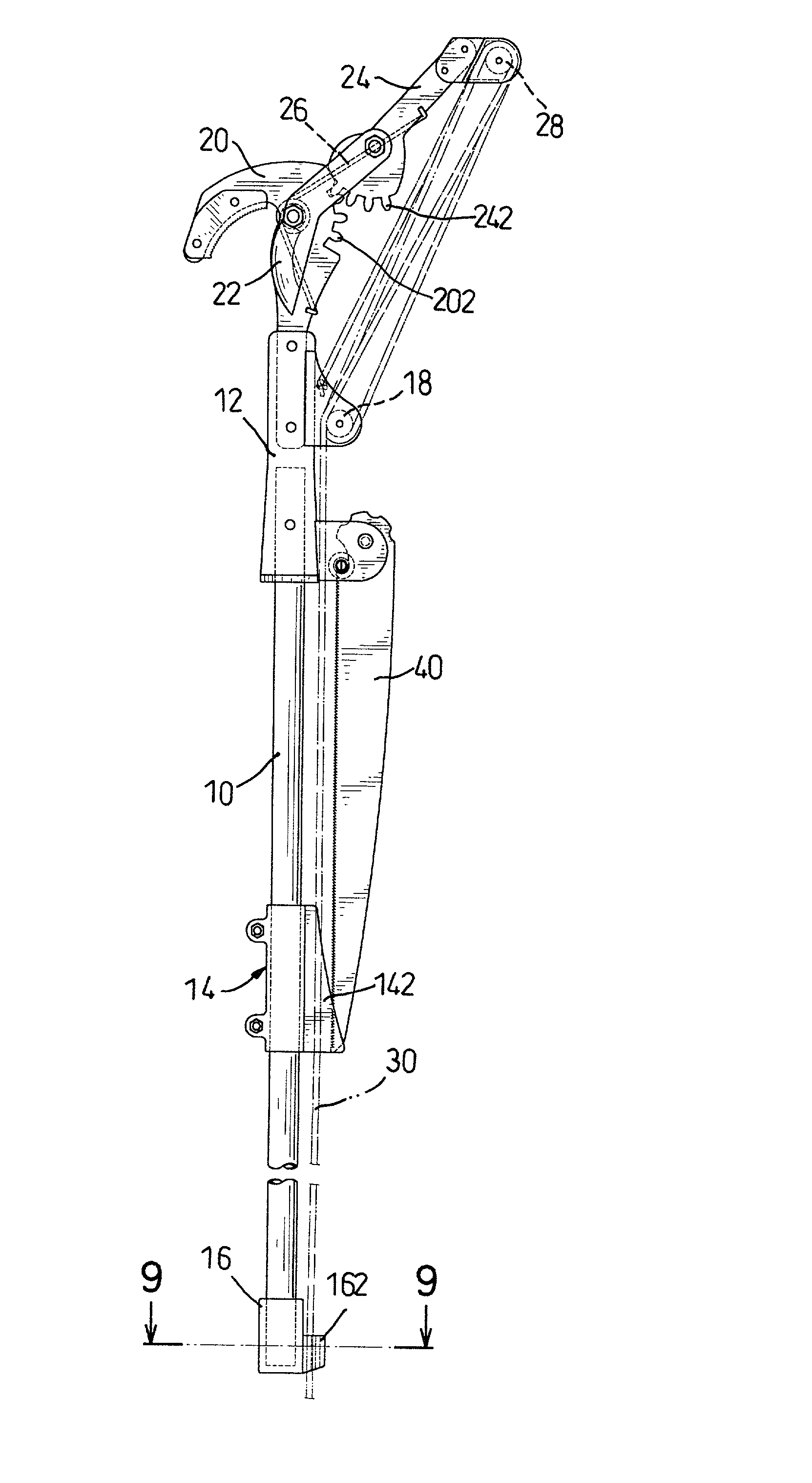
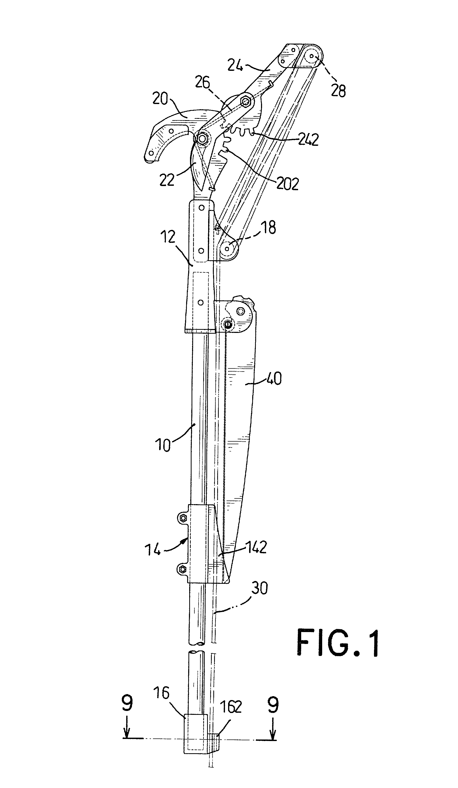
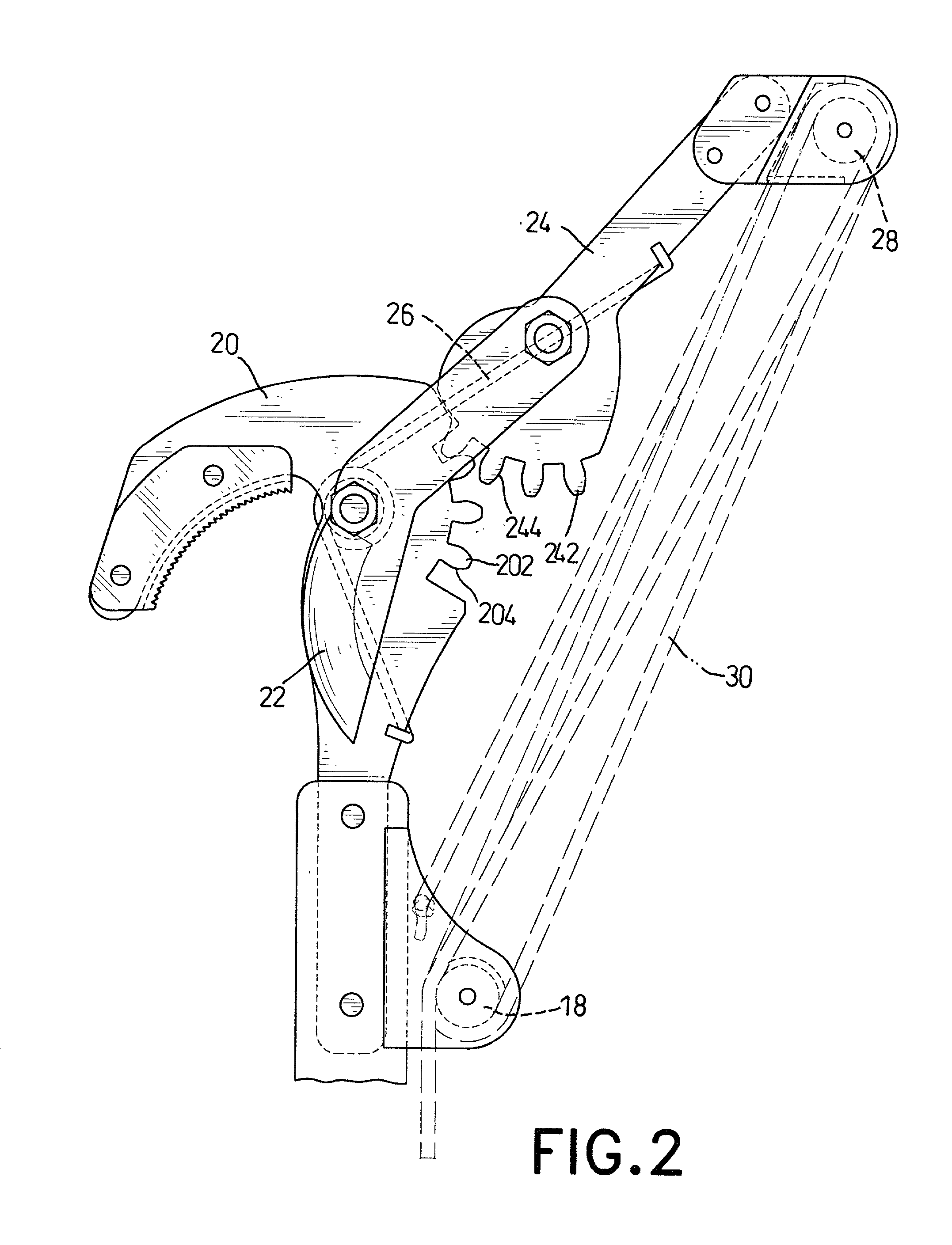
[0019] With reference to FIGS. 1 and 2, a tree pruner in accordance with the present invention comprises a support rod (10), a cutting set and a pull cord (30). The cutting set is mounted on the top end of the support rod (10) through an upper holder (12), wherein the upper holder (12) is secured on the top end of the support rod (10). Two lower pulleys (18) are rotatably mounted on the upper holder (12). The cutting set comprises a fixed blade (20), a cutting blade (22) and a driving lever (24). The fixed blade (20) is secured to the upper holder (12), and the cutting blade (22) is pivotally attached to the fixed blade (20). Both the fixed blade (20) and the cutting blade (22) have a blade portion corresponding to each other. Multiple fixed teeth (202) are formed on one edge of the fixed blade (20) far from the blade portion of the fixed blade (20). The driving lever (24) is pivotally attached to the cutting blade (22) at the end far from the blade portion of the cutting blade (22)...


PUM


Abstract

A tree pruner has a support rod, a cutting set and pull cord. The cutting set is mounted on the top end of the support rod and has a fixed blade, a moving blade and a driving lever. The fixed blade is securely connected to the top end of the support rod and has multiple fixed teeth formed on an edge of the fixed blade. The cutting blade is pivotally attached to the fixed blade. The driving lever is pivotally attached to one end of the cutting blade and has multiple moving teeth formed on the driving lever to engage with the fixed teeth on the fixed blade. With such a cutting set, the travel of pulling the pull cord can be increased, such that the cutting set can cut off with ease a tree part with a large diameter.

Description

BACKGROUND OF THE INVENTION[0001] 1. Field of the Invention[0002] The present invention relates to a tree pruner, and more particularly to a tree pruner that can prune a tree with ease.[0003] 2. Description of Related Art[0004] To cut off a dead or a living part of a tree, a tree pruner with a rod is used so that it is not necessary to climb the tree and the user can easily trim the tree at a low location. With reference to FIG. 10, a conventional tree pruner in accordance with the prior art comprises a support rod (60), a cutting set (62) and a pull cord (64). The cutting set (62) is arranged on a top end of the support rod (60) and comprises a fixed blade (622), a cutting blade (624) and an actuating link device (626). The fixed blade (622) is secured to the top end of the support rod (60), and the cutting blade (624) is pivotally attached to the fixed blade (622). Both the fixed blade (622) and the cutting blade (624) have a blade portion corresponding to each other. The actuatin...

Claims


Application Information

Patent Timeline
25 Sep 2003
Publication
US20030177644A1
IPC
A01G3/025
CPC
A01G3/0255
Inventors
CHENG, KUN-CHIA