Method for controlling fusion pipe sag

Inactive Publication Date: 2003-10-16
CORNING INC
View PDF5 Cites 50 Cited by
  • Summary
  • Abstract
  • Description
  • Claims
  • Application Information

AI Technical Summary

Problems solved by technology

Both of these approaches suffer from the basic problem that an aperture in a fusion pipe weakens the pipe, which makes it more prone to sagging and can lead to other problems, e.g., crack formation, under the demanding environmental conditions in which fusion pipes are used.
Because

Method used


Image

  • Method for controlling fusion pipe sag
  • Method for controlling fusion pipe sag
  • Method for controlling fusion pipe sag

Examples


Embodiment Construction

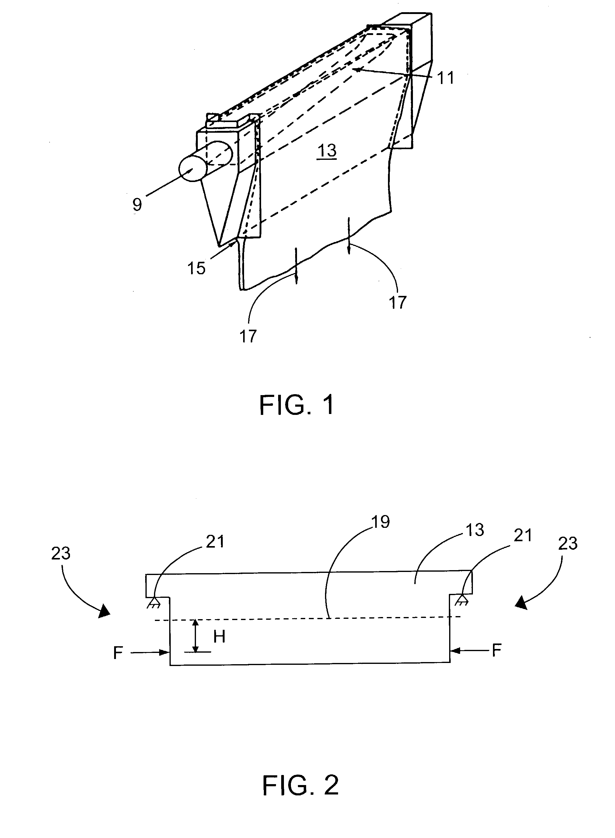
[0034] Overflow downdraw fusion pipes composed of isostatically pressed zircon were tested under service conditions with and without the application of sag-controlling axial forces.

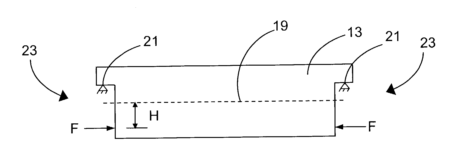
[0035] In these experiments, the fusion pipe was symmetric about the frontal plane and the sag-controlling forces were also symmetric about that plane. Specifically, the sag-controlling forces were applied substantially uniformly to corresponding areas at the ends of the pipe, the centers of which were at the frontal plane.

[0036] The force was applied to one end of the pipe using an air cylinder with the other end held stationary. The magnitude of the force generated by the air cylinder was approximately 33,000 newtons and was centered at a point approximately 12 centimeters below the neutral axis. The fixation of the opposite end of the pipe was centered the same distance below the neutral axis. The moments applied to the ends of the pipe were thus each approximately 4,000 newton-meters. The magnitude of...


PUM


Abstract

The sag rate of fusion pipes (e.g., isopipes (<bold>13</highlight>) used in an overflow downdraw fusion process) is reduced by the application of axial forces (F) to the end regions (<bold>23</highlight>) of the pipe. The axial forces are applied to the end regions below the pipe's neutral axis (<bold>19</highlight>) so that a bending moment is generated which opposes gravitational sagging of the middle of the pipe. The use of such sag-controlling axial forces increases pipe service life by, for example, at least a third.

Description

[0001] This invention relates to fusion pipes used in the production of sheet glass and, in particular, to techniques for controlling the sag which such pipes exhibit during use.[0002] The fusion process is one of the basic techniques used in the glass making art to produce sheet glass. See, for example, Varshneya, Arun K., "Flat Glass," Fundamentals of Inorganic Glasses, Academic Press, Inc., Boston, 1994, Chapter 20, Section 4.2., 534-540. Compared to other processes known in the art, e.g., the float and slot draw processes, the fusion process produces glass sheets whose surfaces have superior flatness and smoothness. As a result, the fusion process has become of particular importance in the production of the glass substrates used in the manufacture of liquid crystal displays (LCDs).[0003] The fusion process, specifically, the overflow downdraw fusion process, is the subject of commonly assigned U.S. Pat. Nos. 3,338,696 and 3,682,609, to Stuart M. Dockerty, the contents of which a...

Claims


Application Information

Patent Timeline
IPC IPC(8): C03B17/06C03B17/00
CPCC03B17/064C03B17/06
Inventor MEDA, GAUTAMPOWELL, WILLIAM R.RHOADS, RANDY L.
Owner CORNING INC
Why Eureka
Try Eureka