Method for the injection molding and successive decoration molding for a molded product

a technology of injection molding and molding product, which is applied in the direction of molding, manufacturing tools, ceramic shaping apparatus, etc., can solve the problems of temperature difference in limited molding time, considered technically difficult to elevation control, and conventional molding method that employs injection cavity molds for the two types of molding

Inactive Publication Date: 2003-10-23
NIPPON BEE CHEM +1
View PDF17 Cites 30 Cited by
  • Summary
  • Abstract
  • Description
  • Claims
  • Application Information

AI Technical Summary

Problems solved by technology

It is considered technically difficult to elevation control such the temperature difference in a limited molding time.
Therefore, the conventional molding method that employs the injection cavity mold commonly for the two types of molding has a problem because it is hardly utilized in decoration molding using a thermosetting coating material.
In addition, the formation of the space by the retreat of the core is limited in between opposing surfaces: a front surface of the molded product and a surface of the cavity.
Therefore, it is impossible to mold a decorative film over vertical sides of a box-like molded product, resulting in a problem because the decoration molding is restricted in products molded in limited shapes.
Therefore, it is impossible to form a gate for injecting a coating material in between the parting faces to employ it as a side gate for injecting the coating material through an opening edge of the molded product.
Thus, injection is performed inevitably through a gate designed at the top center, resulting in a gate trace in the top of the product.
The gate trace often causes an outer design defect depending on the product.
This need causes a problem because a mold structure is complicated.
If it has a composition that contains a volatile component with a boiling point below the thermosetting temperature, a problem is easily caused when the volatile component vaporizes.
If it takes a long time to complete the injection, the thermosetting of the coating material 41a advances from the cavity-surface side before completion of the injection, forming weld and causing mottle due to unevenness in a decorative agent such as aluminum powder.

Method used


Image

  • Method for the injection molding and successive decoration molding for a molded product
  • Method for the injection molding and successive decoration molding for a molded product
  • Method for the injection molding and successive decoration molding for a molded product

Examples


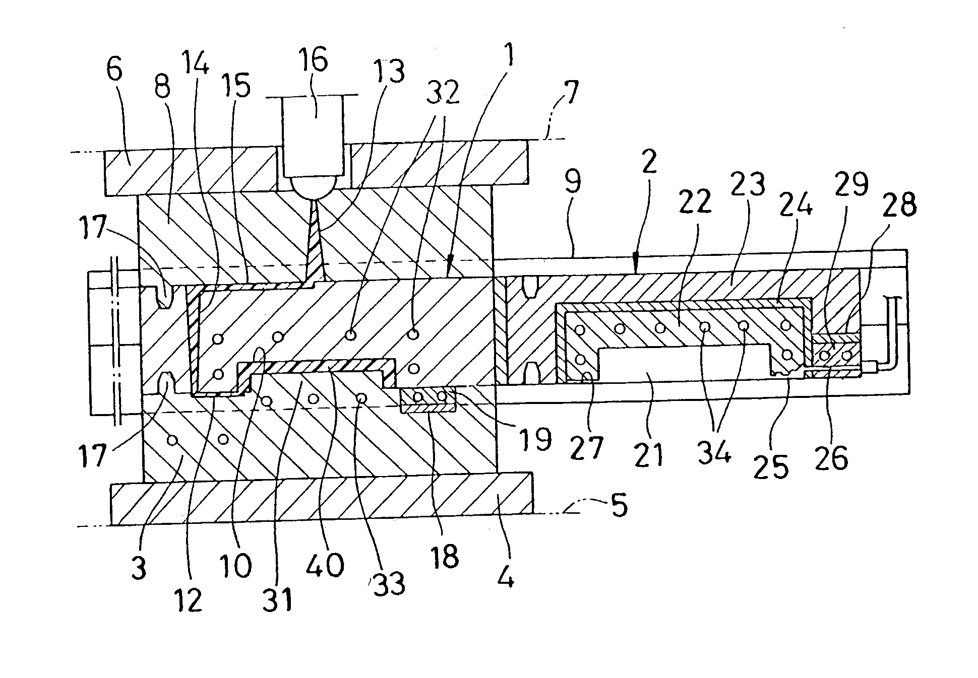
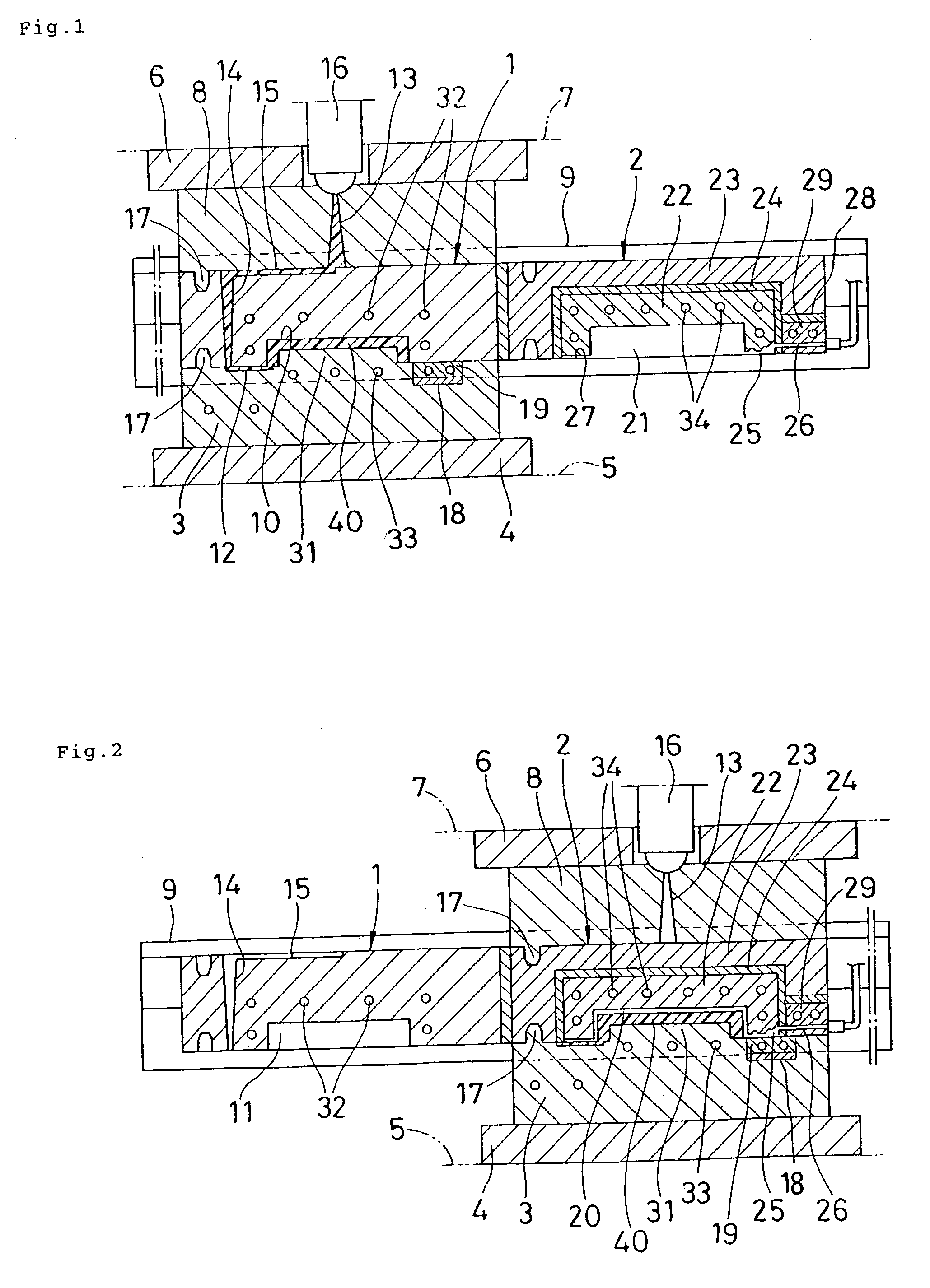
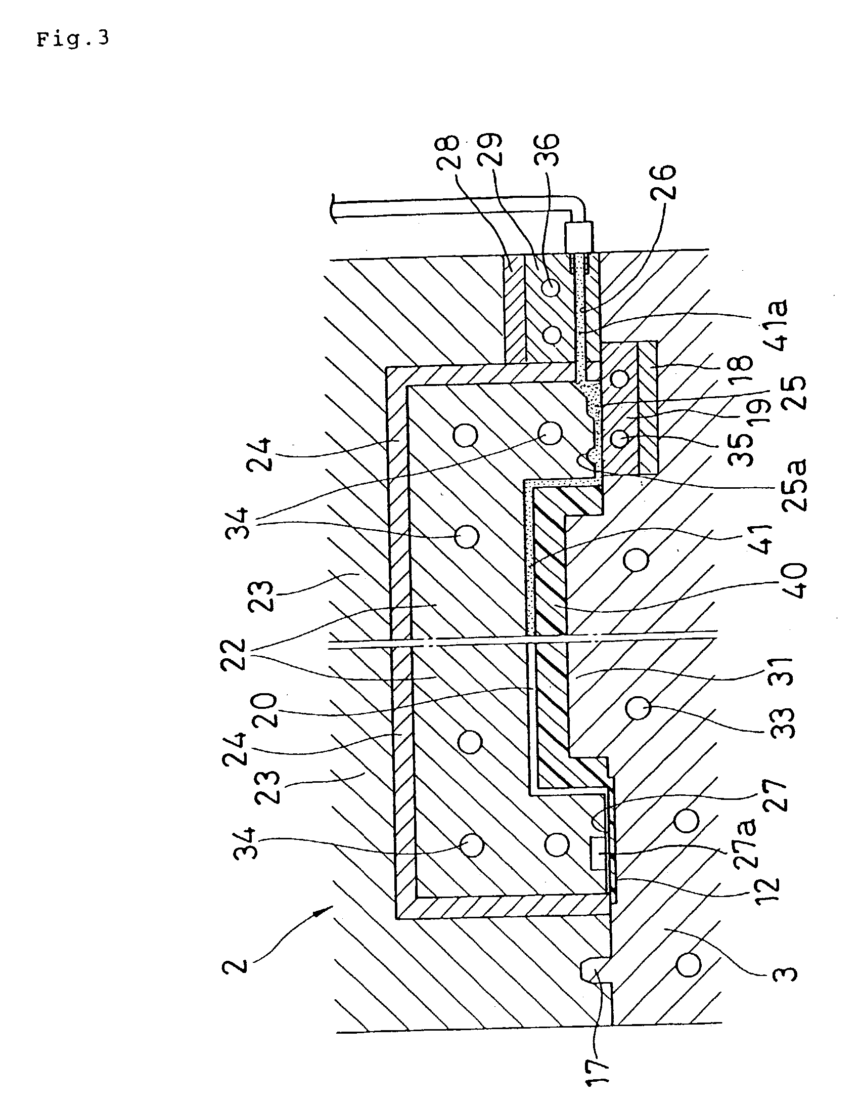
Embodiment Construction

[0052]

1 Material of Molded product: Polypropylene Shape of Molded product: Box type, 150 wide .times. 210 deep .times. 20 mm high Thickness of Molded product: 2.5 mm Coating material: KX-1031A (Silver metallic), Trade name of Nippon Bee Chemical Co., Ltd. JAPAN Viscosity: 10,000 mPa's at 25.degree. C., 6 rpm Measured by B-type viscometer made by TOKIMEC INC. JAPAN Thickness of Decorative film: 100 .mu.m Molding machine used: ES3000-25E (Mold slide replacement Trade name of Nissei Plastic Industrial Co., Ltd. Temperature in Injection cavity mold: 80.degree. C. Temperature in Core mold: 80.degree. C. Clamping mold force (Injection molding): 126 tonf Molding time: 60 sec Space set in Decoration cavity mold: 100 .mu.m Gate space in Injection inlet: 100 .mu.m Resin pool: 2.0 .mu.m Gate width of Injection inlet: 160 .mu.m Gas vent: 10 .mu.m Temperature in Decoration cavity: 120.degree. C. Temperature in Injection inlet: 120.degree. C. Temperature in Injection path: 30.degree. C. Clamping ...


PUM

PropertyMeasurementUnit
temperatureaaaaaaaaaa

Abstract

Injection molding of a product and decoration molding of a surface of the molded product are performed using individual cavity molds. A decorative film can be molded efficiently with a thermosetting coating material under suitable temperature control regardless of the shape of the molded product. An injection cavity mold and a decoration cavity mold are employed. The injection cavity mold is set at a hardening temperature of a thermoplastic resin. The decoration cavity mold is set at a thermosetting temperature of a coating material. A molded product is formed by injection molding in the injection cavity mold. The injection molded product is located within the decoration cavity mold to create a space as a cavity for decoration molding between an inner surface of the decoration cavity mold and a surface of the injection molded product. A decorative film is molded over the surface of the injection molded product by injecting a decorative coating material composed of a liquid thermosetting composition into the cavity under pressure. The coating material is composed of a liquid thermosetting composition that substantially contains no volatile component having a boiling point below the thermosetting temperature set on the cavity mold for decoration molding.

Description

[0001] 1. Field of the Invention[0002] The present invention relates to a method of injection molding of a molded product using a synthetic thermoplastic resin, and successive decoration molding of a decorative film over a surface of the molded product using a coating material in cavity molds respectively.[0003] 2. Description of the Related Art[0004] In a method so-called In-Mold Coat Molding, a decorative film of a coating material is molded over a surface of a molded product of a synthetic resin. In this method, a cavity mold for the injection molding is also used as that for the decoration molding.[0005] For example, JP 2001-38783A discloses a conventional molding method, which comprises providing an injection cavity mold and a core to form a cavity for a molded product; injecting a melted resin fully into the cavity to form the molded product; moving the core slightly backward to form a desired space between the surface of the molded product and the surface of the cavity; and i...

Claims


Application Information

Patent Timeline
Patent Type & Authority Applications(United States)
IPC IPC(8): B29C45/16
CPCB29C45/0416B29C45/1679B29C45/1615
Inventor KITAMURA, AKIHIROIIJIMA, NOBUOSAITOU, YOSHIHIKOOKADA, HARUOIKEDA, TORU
Owner NIPPON BEE CHEM
Why Eureka
Try Eureka